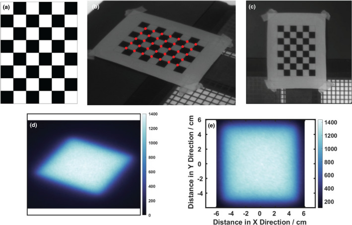
Figure 2.

In (a) the square patterned board used for calibration is illustrated, with (b) a calibration image taken from camera showing the corners detected (red dots) using the OpenCV library, and remapped (c) to be projected as the undistorted board image. In (d) a Cherenkov image of a 10 × 10 cm2 beam is shown, and (e) the remapped Cherenkov image is shown as a square [Color figure can be viewed at wileyonlinelibrary.com]
