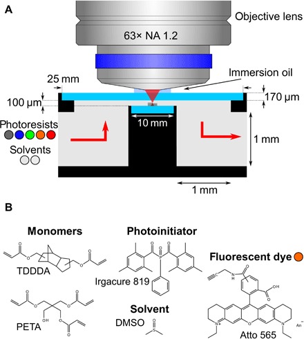
Fig. 1. Scheme of the microfluidic chamber.

(A) A high-NA oil-immersion microscope objective lens focuses femtosecond laser pulses into a chamber, which is clad by two thin glass windows (light blue). One of them serves as the substrate for the samples. The selection valve shown in Fig. 3 allows for switching between different photoresists (here, one nonfluorescent and four fluorescent) and solvents (acetone and mr-Dev 600), which are injected into the microfluidic chamber. For clarity, the scheme is not to scale. A to-scale technical drawing is shown in Fig. 2B. (B) Structure formulae of the components of one of the fluorescent photoresists containing Atto dye molecules.
