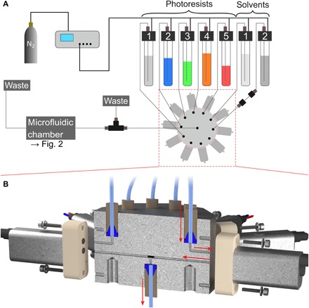
Fig. 3. Scheme of the system connected to the microfluidic chamber.

(A) It consists of an electronic pressure controller connected to a nitrogen bottle, up to 10 containers for the photoresists and solvents for development, and the star-shaped selection valve. Pumping individual liquids is possible by applying a pneumatic pressure to all liquid containers and opening the flow path for a single liquid using the selection valve. Following the selection valve, the liquid flow is guided through an overpressure valve and our homebuilt sample holder. Last, it is directed into a waste container. (B) Cross section through our homebuilt selection valve assembly. The assembly consists of commercial solenoid valves and a homebuilt 10-to-1 manifold that connects the 10 liquid containers to 10 solenoid valves, and the valve outputs to one manifold output port. An example flow path for one liquid is indicated with red arrows.
