. 2019 Jan 7;19(3):503–512. doi: 10.1039/c8lc01259h

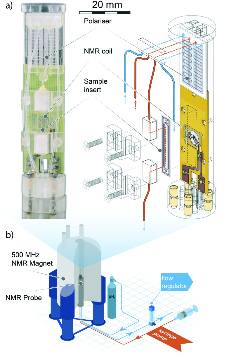
Fig. 1. Top left: Photograph of the micro-SABRE platform mounted on the head of the NMR probe. Top right: Schematic drawing displaying the main components of the micro-NMR platform. Red lines indicate gas flow paths, blue lines are fluidic flow paths. The meandering channel gas–liquid contactor visible at the upper extremity of the platform is described in Fig. 2. Bottom: An overview of the main components of the experimental layout. The gas and solution are pneumatically transported through the NMR probe mounted in an 11.74 T NMR magnet, where the custom probe head insert performs the SABRE experiment. Gas flow is regulated valley-side of the NMR probe to ensure proper pressure equilibration throughout the system. The sample solutions are injected with a standard syringe pump; any excess fluid running out of the detection area is collected in a spill-out chamber inside the NMR probe body. The area of the helmholtz pair is 1.13 mm2, the detection volume enclosed by the coil is 0.56 μL. For a close-up view of the NMR detector refer to section 3 of ESI. .

Fig. 1