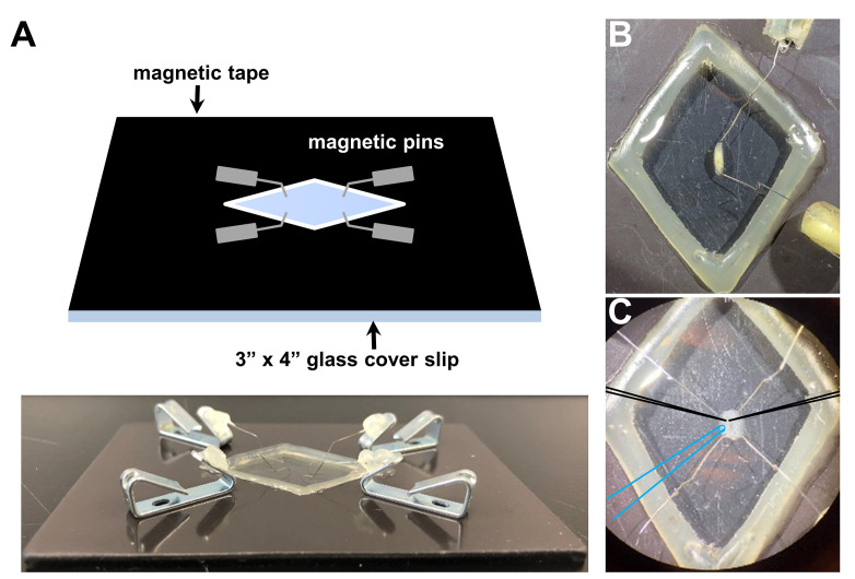
Figure 3. Drosophila larvae before and after dissection in the recording chamber.
A. Representative schematic (top) and picture (bottom) of the recording chamber used for larval dissection and electrophysiology with magnetic pins. Representative images of a third-instar larvae before (B) and after dissection (C) using this system. Note that optimal positioning of recording electrodes (schematized in black) and the stimulation pipette (schematized in blue).

