. 2019 Jan 28;8:e42001. doi: 10.7554/eLife.42001

Figure 1. G40P unwinds DNA in one base pair steps und slips backwards.

(a) Schematic illustration of the smFRET unwinding assay. After loading to the substrate G40P unwinds the dsDNA (containing between 0 and 3 consecutive GC base pairs after 10 AT base pairs) and thereby gradually separates the donor fluorophore from the acceptor fluorophore. Complete unwinding results in donor strand leaving from the surface. (b) Typical unwinding trace of G40P. At tinject the protein solution containing Mg.ATP is injected. The unwinding initiation time tinit depends on the protein concentration and is measured from the moment of protein solution injection until unwinding starts. The unwinding time tunw is determined from the moment of FRET efficiency decrease until donor strand leaving. (c) Typical FRET efficiency unwinding traces of G40P on an all AT substrate base pair. The scale bar indicates 1 s. (d) Typical FRET efficiency unwinding traces of G40P with one GC base pair. The helicase briefly stalls at a characteristic FRET efficiency or slips after stalling and unwinds in a second attempt. (e) Typical FRET efficiency unwinding traces of G40P on the substrate with two consecutive GC base pairs. The helicase stalls eventually at two distinct FRET efficiencies (see arrows). (f) Typical FRET efficiency unwinding traces of G40P on the substrate with three consecutive GC base pairs. The helicase rarely unwinds three consecutive GC base pairs completely (top trace). Most traces show unwinding attempts and stalls at distinct FRET efficiency levels (bottom trace). (g-i) FRET efficiency distribution of stall levels of the one GC (blue), two GC (black) and three GC base pair (red) substrate. A (multipeak) fit with Gaussians revealed one peak at EFRET = 0.52 ± 0.04 for 1GC, two peaks at EFRET = 0.53 ± 0.04 and at EFRET = 0.39 ± 0.04 (two dashed lines) for 2GC and three peaks at EFRET = 0.52 ± 0.04, EFRET = 0.38 ± 0.04 and at EFRET = 0.27 ± 0.04 (three dashed lines) for 3GC. (j) Average FRET efficiencies with stalls after 4AT, 7AT, 10AT and 13AT base pairs (black symbols) in comparison with peak positions of stalls induced by 1GC, 2GC and 3GC base pairs (blue symbols).

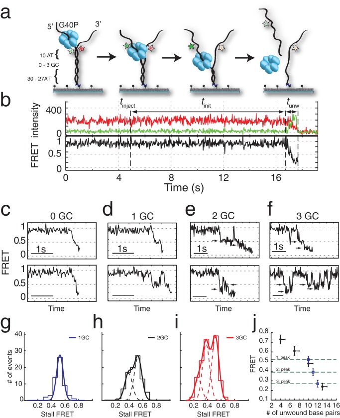
Figure 1.

Figure 1—figure supplement 1. Choice of substrate, data selection, Michaelis-Menten kinetics and kinetic step size of G40P.

Figure 1—figure supplement 1.

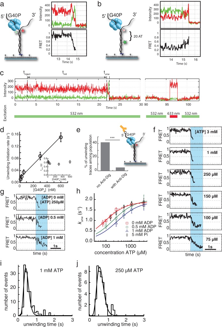
(a) Opposite fluorophore attachment to the forked dsDNA substrate yield a wide FRET change range during unwinding. A typical trace is shown on the right-hand side. (b) Labeling the non-tracking strand with the donor and acceptor fluorophores relies for the FRET efficiency change on the shorter persistence length of ssDNA compared to dsDNA. Both fluorophores do not have to pass through the central pore of the helicase and yield identical average unwinding times. However, the FRET efficiency change signal is much less clear (right). (c) Selection criteria for traces to be included in the analysis. Typical unwinding trace of G40P. At tinject the protein solution together with Mg.ATP is injected. The unwinding initiation time tinit depends on the protein concentration and is measured from the moment of protein solution injection until unwinding starts. smFRET traces were tested for acceptor survival by means of direct excitation with a 633 nm laser to exclude acceptor bleaching events from analysis. During the unwinding assay, only donor molecules were excited with a 532 nm laser. In the illustrated trace, unwinding was observed at t ≈ 22 s, the acceptor test was performed at t ≈ 96–97.5 s. (d) The unwinding initiation rate (1/tinit) is shown as a function of G40P hexamer concentration and can be fitted linearly (errors are standard deviation). Inset: The unwinding time is independent of the protein concentration within error. (e) Percentage of initial high FRET traces with successful unwinding events without anti-digoxigenin and with anti-digoxigenin at the 5’ tail of the forked duplex (*** denotes p<0.001). Inset: Schematic illustration of the digoxigenin-modified substrate (square at the 5’ tail) blocked by anti-digoxigenin (yellow). (f) Typical FRET efficiency unwinding traces at [ATP]=3 mM, 1 mM, 250 µM, 150 µM, 100 µM and 75 µM. The unwinding appears smooth and the unwinding time increased with decreasing ATP concentration. (g) Typical FRET efficiency traces at [ATP]=250 µM and with increasing [ADP]=0 mM, 0.5 mM and 1 mM. The effect of ADP as competitive inhibitor can be directly observed with increasing unwinding times. (h) Semi-logarithmic plot of the average unwinding rate (1/tunw) as a function of ATP concentration (errors are standard deviation). The average unwinding rate at different ATP concentrations was determined without ADP (red squares), with 0.5 mM ADP (green circles), with 1 mM ADP (blue triangles) and 5 mM Pi (black rhomboids). The solid lines are fits to the data using Michaelis-Menten equation. The red dashed is a fit to the 0 mM ADP data with the Hill-equation. (i) Unwinding time distribution of the AT substrate by (G40P)6 at 1 mM ATP. Fit is a Gamma distribution with a stepping rate k = 21.9 s−1 and a number of steps n = 10.1. (j) Unwinding time distribution of the AT substrate by (G40P)6 at 250 µM ATP. The fit is a Gamma distribution with a stepping rate k = 16.4 s−1 and a number of steps n = 10.1.
Figure 1—figure supplement 2. GC induced stalls and unwinding length-FRET calibration.

Figure 1—figure supplement 2.

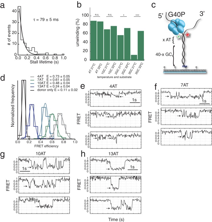
(a) Stall lifetime distribution of G40P stalls on the 1GC substrate. A single exponential fit yields a characteristic lifetime of 79 ± 5 ms. (b) Fraction of all traces with protein activity with complete unwinding on different substrates (AT, 1GC, 2GC, 3GC) and at 21°C and 33°C, respectively (n.s. denotes not significant, *p<0.05, ***p<0.001). (c) Sketch of the intrinsic calibration constructs with x AT base pairs followed by 40-x GC base pairs. Due to its exquisite sequence sensitivity G40P stalls at the GC base pairs. (d) Stall FRET level histograms for four different substrates: 4AT, 7AT, 10AT and 13AT. The Histograms were evaluated with Gaussian fits. The leakage of donor fluorescence to the acceptor channel was determined to give an apparent EFRET = 0.11 ± 0.02. (e) through (h) Sample traces of calibration substrates 4AT, 7AT, 10AT and 13AT, respectively, with the analyzed stall level indicated by arrows.
Figure 1—figure supplement 3. Unwinding traces of the AT DNA substrate by (G40P)6 in presence of 1 mM ATP and 10 mM CaCl2 instead of 10 mM MgCl2.

Figure 1—figure supplement 3.

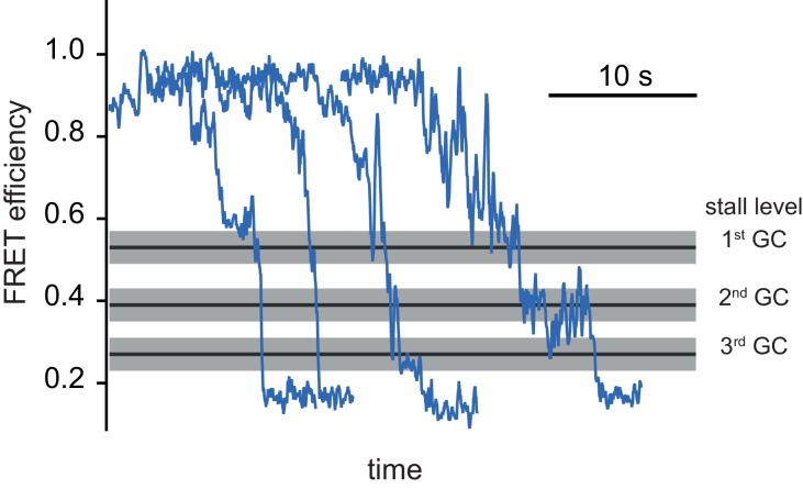
Traces are offset for clarity. Black lines and grey shade represent the stall FRET efficiency levels of the consecutive GC base pairs at position 11, 12 and 13 for reference of consecutive FRET levels.