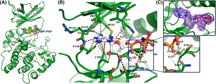
Figure 2.

Crystal structure of VRK1–AMP‐PNP complex. (A) The cartoon representation of VRK1 bound to AMP‐PNP, in ball and stick mode, and a magnesium ion (Mg), shown as a green sphere. The major secondary structure elements are labeled for reference. (B) The interactions made by AMP‐PNP (shown in ball and stick), with the active residues of VRK1 (shown in stick mode). The hydrogen bonds and non‐polar interactions are shown as black and brown broken lines, respectively. The Mg ion (in green sphere) form a coordination geometry with AMP‐PNP phosphate groups and nearby Asp197 and Asn182 (shown as inset). (C) The 2Fo–Fc electron density map, contoured at 1σ cut‐off, showing density cover for all the atoms of AMP‐PNP and the co‐ordinated Mg ion.
