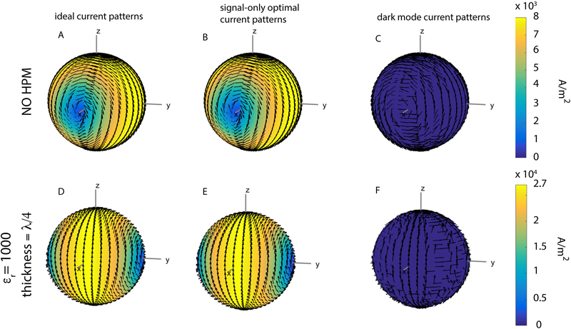
Figure 2:
Snapshots at time zero of various current patterns optimized for the central voxel. Arrows indicate surface current direction, and current amplitude is indicated by color, with yellow being high and blue being low. The ideal current patterns and the signal-only optimal current patterns are identical, and the dark mode current patterns are vanishingly small, for this central voxel, both for the case without HPM (A-C) and for the case with an HPM layer with relative permittivity εr =1000 and thickness = λ/4 (D-F). In the presence of HPM (D, E), the current patterns exhibit a rotational phase shift with respect to the patterns in the absence of HPM, and current amplitude is higher in the presence of HPM (note the different colorbar limit).

