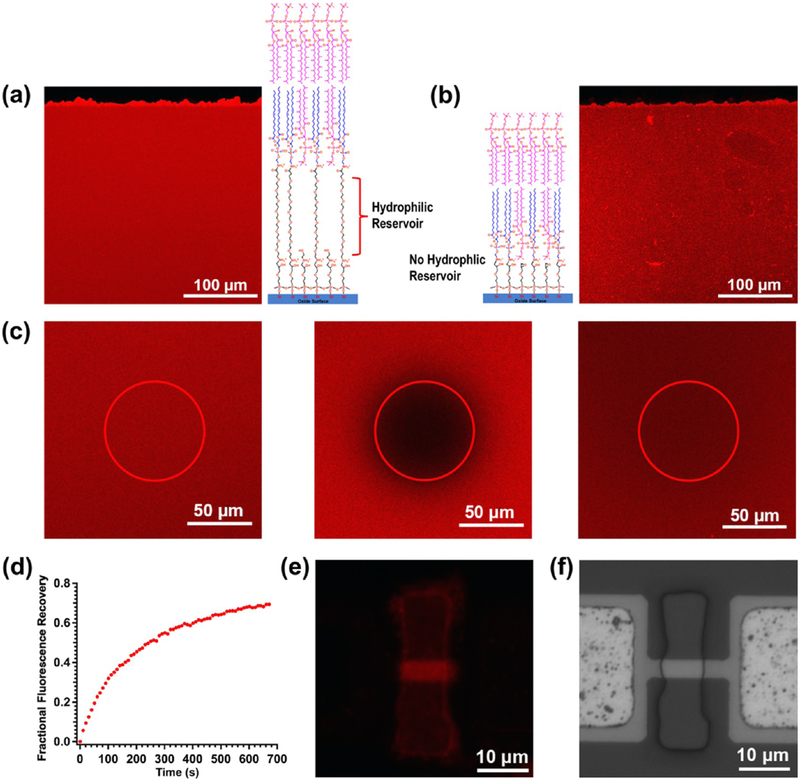
Figure 3.
Fluorescence images of the two types of tBLMs, respectively, formed on GOPS-CA(PEG)8-DOPE (a) and GOPS-DOPE (b) functionalized glass slides, FRAP images (c) of the tBLM shown (a) before (left), immediately after (middle), and 670 s (right) after photobleaching, and the corresponding FRAP recovery curve (d). The fluorescence image (e) and the corresponding bright field image (f) of a silicon nanoribbon device after tBLM formation on a GOPS-CA(PEG)8-DOPE-functionalized surface.

