Abstract
This paper presents the design evolution, fabrication, and testing of a novel patient and organ-specific, 3D printed phantom for external beam radiation therapy of prostate cancer. In contrast to those found in current practice, this phantom can be used to plan and validate treatment tailored to an individual patient. It contains a model of the prostate gland with a dominant intraprostatic lesion, seminal vesicles, urethra, ejaculatory duct, neurovascular bundles, rectal wall, and penile bulb generated from a series of combined T2-weighted/dynamic contrast-enhanced magnetic resonance images. The iterative process for designing the phantom based on user interaction and evaluation is described. Using the CyberKnife System at Boston Medical Center a treatment plan was successfully created and delivered. Dosage delivery results were validated through gamma index calculations based on radiochromic film measurements which yielded a 99.8% passing rate. This phantom is a demonstration of a methodology for incorporating high-contrast magnetic resonance imaging into computed-tomography-based radiotherapy treatment planning; moreover, it can be used to perform quality assurance.
1. INTRODUCTION
Radiation therapy is a regular and proven treatment option for early-stage, localized prostate cancer. One of the main approaches is external beam radiation therapy (EBRT) in which beams of radiation generated by a medical linear accelerator are delivered in a calculated optimal pattern through the body into the prostate within a defined margin. The goal of the treatment is to deliver a prescribed dose of radiation to a specific tumor target volume while minimizing absorption in the neighboring non-cancerous tissue. A variety of EBRT techniques have been developed to increase clinical effectiveness by delivering higher, more localized doses of radiation over shorter periods of time [1]. The results are better patient outcomes in terms of eliminating the cancer cells while sparing healthy surrounding tissue so as to minimize undesirable adverse side effects.
Accurate and precise identification of the boundaries of the prostate, clinically relevant intra- and periprostatic structures (e.g., urethra, rectal wall, neurovascular bundles), and target lesions during treatment planning enables accurate delivery of high-dosage radiation to the planning target volume (PTV), which encompasses the lesion and a small margin with a steep drop-off gradient beyond the boundary. Beam path and dose calculations are based on computed tomography (CT) imaging which provides measurement of electron density [2]; however, delineation of structures can be difficult and inconsistent because soft tissue contrast in CT is often not sufficiently well-defined. In comparison, magnetic resonance (MR) imaging can show very high soft-tissue contrast allowing clear delineation of structural boundaries. It would be natural to combine treatment planning based on both CT and MR imaging but this, currently, is not done in standard practice of conventional EBRT due to challenges with image integration [3–4].
This work demonstrates a methodology that combines the two imaging modalities for treatment planning by using a physical, 3D-printed phantom created from a patient’s MR images. CT-based EBRT treatment planning can be performed on these phantoms using existing clinical systems. In addition, the capability to perform radiation dose quality assurance (QA), a critical requirement of every plan review, is incorporated into the phantom.
Currently, commercial pelvic phantoms (e.g., Standard Imaging Inc., Middleton, WI, CIRS Inc., Norfolk, VA, ScandiDos, Uppsala, Sweden) are available specifically for dosage QA but are not generally configurable and cannot be used for patient treatment planning. Paliwal et al. [5] created a solid water (plastic with radiodensity equivalent to water) pelvis phantom with epoxy/solid water-filled volumes to represent the prostate, bladder, rectum and femoral heads. Cylindrical grooves were machined into the phantom for placement of ionization chambers and thermoluminescent dosimeters (TLDs). Followill et al. [6] created a pelvis phantom consisting of a water-filled shell with interchangeable inserts for imaging and dosimetry. The imaging insert was itself a water-filled shell containing representations for the prostate (nylon sphere), bladder (polyethylene sphere), rectum (wax cylinder), and rectal wall (polyethylene tube). The dosimetry insert held radiochromic film and TLDs. The pelvis phantom created by Harrison et al. [7] was based on the anatomy of an example patient. It was milled from solid polyurethane-based material into slabs with fill-ins for bone and organs and spaces to accommodate ionization chambers and TLDs.
The use of 3D printing to fabricate spatially-complex phantoms is a natural application of this technology. Three-dimensional objects have been printed based upon CAD models generated from medical images (e.g., CT, MR) [8–10]. Kumar et al. [11] used prostate MR images to create 3D-printed, patient-specific molds to process radical prostatectomy specimens. Furthermore, thermoplastics commonly used by commercial 3D printers (e.g., ABS-acrylonitrile butadiene styrene) have radiodensities comparable to water and can, therefore, stand in for soft tissue when used in QA phantoms [12–14]. Ehler et al. [15] created and tested a 3D-printed head and neck-region phantom for intensity modulated radiation therapy QA.
This paper presents the design evolution, fabrication, and testing of a novel pelvic phantom containing a patient-specific, 3D-printed, ABS model of the prostate gland with a dominant intraprostatic lesion (DIL), seminal vesicles, urethra, ejaculatory duct, neurovascular bundles, rectal wall, and penile bulb generated from a series of combined T2-weighted/dynamic contrast-enhanced MR images. In contrast to existing phantoms, this phantom can be used to plan and validate EBRT treatment tailored for an individual patient. Design goals for the phantom were to create a system that is easily adaptable to multiple patients, quick to fabricate, simple to use, and provides repeatable measurements. Ergonomic considerations were taken into account as well as strength and stiffness requirements. The performance of the phantom for treatment planning and QA was evaluated with the CyberKnife System (Accuray Inc., Sunnyvale, CA) at Boston Medical Center. The sections following present: the process for creating 3D CAD and printed models from MR images, the design evolution of the pelvis phantom, and the testing and evaluation of the phantom for treatment planning and QA.
2. 3D MODEL GENERATION
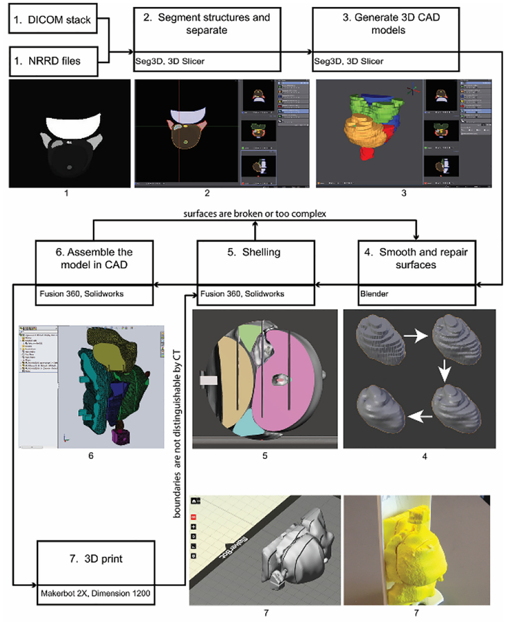
Figure 1 shows the process workflow that was developed for creating 3D CAD and printed models from MR images. A combination of commercial and open source software was used. In some cases, a process step was repeated with multiple software packages to compare performance or ease-of-use. The following steps correspond to Figure 1.
Fig. 1.
Process workflow diagram for creating 3D CAD and printed models based on a patient’s MR images. Seven commercial and open source software programs are involved: Seg3D, 3D Slicer, Blender, Meshmixer, Fusion 360, SOLIDWORKS, and MakerBot Desktop.
Step 1: Begin with the patient’s images.
The prototypes presented in this paper are based upon MR images that were taken from a data set (ProstateDx-01–0021) available in the Prostate-Diagnosis Collection of The Cancer Imaging Archive [16–17]. The data set contains both MR images (DICOM file format) and corresponding files (NRRD) which contain contours of the prostate gland, urethra, neurovascular bundles, ejaculatory duct, seminal vesicles, rectum wall, penile bulb, and dominant intraprostatic lesion. There are 23 axial cross-sections that are 5 to 6 mm apart.
Step 2: Segment structures and separate into individual files.
For the patient case presented herein, the structures were already segmented and only needed to be separated into separate files (NRRD). In general, each structure of interest would have to be hand-contoured using color thresholding on each scan using software such as 3D Slicer [18] or SEG3D [19].
Step 3: Generate three-dimensional CAD models.
A three-dimensional model was created for each part by generating isosurfaces between cross-sections. The surfaces were combined into one (STL). The mesh was decimated without loss of detail (determined by inspection) using 3D Slicer and Seg3D.
Step 4: Smooth and repair surfaces.
Using Blender [20], a volume preserving Laplacian smoothing operation which minimized overall shape change was applied to the step discontinuities between cross-sections. Each part was then repaired, remeshed and decimated. The urethra and ejaculatory duct were combined into one model for this step.
Step 5: Add or thicken shells.
So that structural boundaries, specifically around the DIL, would clearly stand out in CT imaging, shells around volumes were added or thickened using Meshmixer (Autodesk Inc., San Rafael, CA) or Fusion 360 (Autodesk Inc., San Rafael, CA).
Step 6: Create assembly with CAD software.
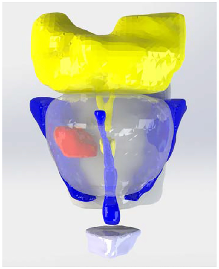
Once the individual models (Parasolids) were smoothed, repaired, and shelled, they were imported into SOLIDWORKS (Dassault Systèmes SOLIDWORKS Corp., Waltham, MA) or Fusion 360 where edits could be made to improve printability and durability and for integration with other components of the phantom. A CAD render of the assembled prostate and intra- and periprostatic structures is shown in Fig. 2. The prostate gland is clear and the DIL is solid red.
Fig. 2.
CAD render of assembled model: prostate gland (clear), dominant intraprostatic lesion (red), seminal vesicles and ejaculatory duct (yellow), urethra and neurovascular bundles (blue), rectal wall and penile bulb (white)
Step 7: 3D print the model.
All of the anatomy-model prototypes were printed on dual-extrusion Replicator 2×’s (MakerBot Industries LLC, Brooklyn, NY). The parts were laid out using Makerbot Desktop (or Meshmixer). Printing was done using ABS material at a resolution of 0.2 mm and an infill of 100%. High impact polystyrene, dissolvable in D-Limonene, was used as the support material. Associated components were printed on Dimension SST 1200es (Stratasys Ltd., Eden Prairie, MN) fused deposition modeling machines.
3. DESIGN EVOLUTION OF THE PHANTOM
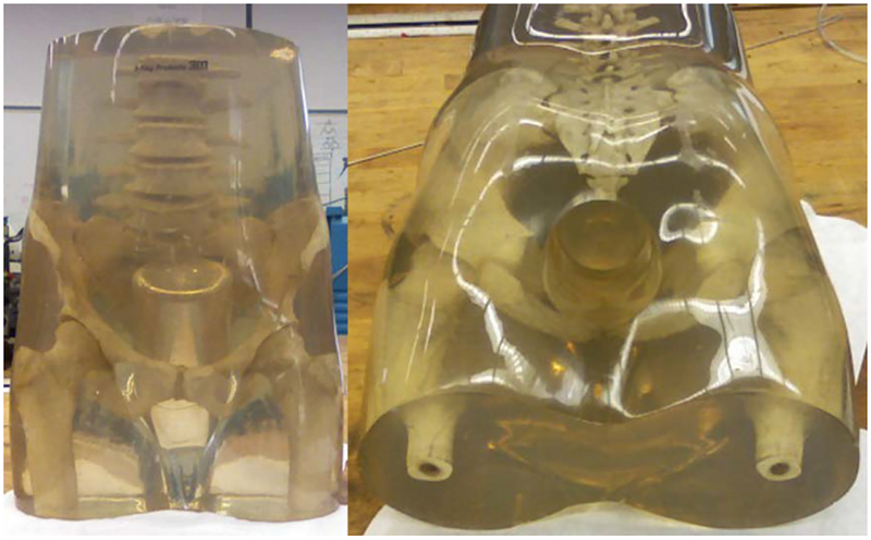
The treatment planning and QA phantom has two parts: the pelvis base and the pelvis-base cartridge. The anthropomorphic pelvis base, shown in Fig. 3, is a clear thermoplastic acrylic with radiodensity equivalent to that of soft tissue and encases skeletal bone. A cylindrical passage was drilled into the base at an appropriate angle to accommodate an insertable cartridge. The design evolution of the pelvis-base cartridge was an iterative process driven by feedback and recommendations from physicians and physicists working with the phantom.
Fig. 3.
Anthropomorphic pelvis base with cylindrical passage drilled out for the pelvis-base cartridge. The radiodensity of the clear, thermoplastic acrylic is equivalent to that of soft tissue.
3.1. Pelvis-Base Cartridge, Version 1: Film Holder Only.
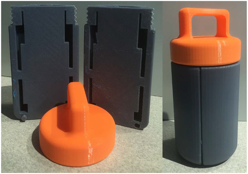
The first version of the pelvis-base cartridge is a direct transition from a related design for holding TLDs [21–22] to one for radiochromic film. CAD renders are shown in Fig. 4. 3D-printed prototypes are shown in Figs. 5 and 6. Two configurations of the cartridge were designed to hold film: one in an axial orientation and the other in either a coronal or sagittal orientation (by 90 degree rotation of the holder). As with the TLDs, the film slices can be positioned in space to pass through points of interest (e.g., lesion, rectal wall) by overlaying and comparing CAD models of the holder and of the patient’s anatomy.
Fig. 4.
CAD renders of the pelvis-base cartridge, version 1 film holder: axial (left) and coronal-sagittal (right)
Fig. 5.
Printed prototype of pelvis-base cartridge, version 1, axial orientation. The outer diameter and length of the main body (yellow) are 6.35 cm and 15.87 cm, respectively. The length of the adjustable end cap (black and pink) as shown is 8.25 cm.
Fig. 6.
Printed prototype of pelvis-base cartridge, version 1, coronal-sagittal orientation
Circular film slices (see Fig. 4) are placed in the axial-orientation holder between sections which screw together. A printed prototype is shown in Fig. 5. Multiple slices could easily be accommodated with multiple sections. For the coronal-sagittal-orientation holder, rectangular film slices are placed between sections (e.g., two as seen in Figs. 4 and 6) which are set into position with alignment pins. All of the sections are held in place by a screw-on endcap (see Fig. 6) with a pull handle. On the other end of the canister, another screw-on endcap (see Fig. 5) can be used to adjust the length of the cartridge for fine positioning within the pelvis base. The interior of the cartridge is hollow and would be filled with water during use. The outer wall of the cartridge is slotted to minimize frictional contact during insertion into the pelvis base. The cartridge, printed with a 50% infill, was not watertight.
3.2. Pelvis-Base Cartridge, Version 2: Combined Imaging-Model and Film Holder.
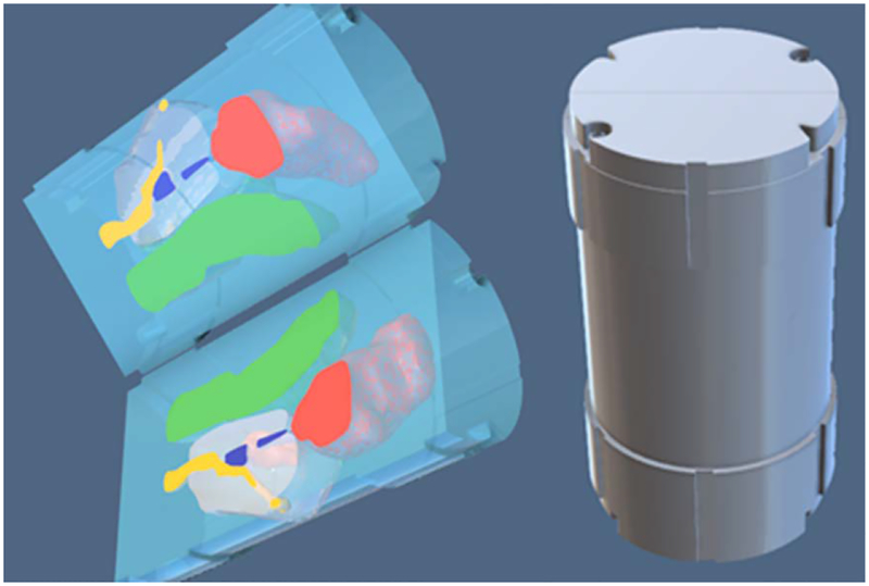
The intent of the second iteration was to expand the functionality of the pelvis-base cartridge to include a full scale, 3D-printed model of the patient’s prostate and intra- and periprostatic structures that could be imaged by CT. Figures 7 and 8 show CAD renders and a printed prototype of a single-film-section, coronal-sagittal-orientation cartridge, respectively. The prostate and intra- and periprostatic structures are embedded in the solid cylindrical body of the cartridge. In this case, there is no empty space that must be filled with water. Film is placed onto one side of a cartridge section in a unique orientation via alignment pegs and a corner notch. Sections snap together and are held in place with a separate retaining clip. To minimize contact friction between the cartridge and the pelvis base, only two 2.5 mm long sections at the top and bottom of the outer wall contact the base. This design could also be modified to accommodate screw-on end caps for positioning and to add a handle. Although the colors of the cartridge and patient’s anatomy are different, they are the same type of plastic and, therefore, are not distinguishable in CT images.
Fig 7.
CAD renders of pelvis-base cartridge, version 2, coronal-sagittal orientation
Fig. 8.
Printed prototypes of pelvis-base cartridge, version 2, coronal-sagittal orientation. The outer diameter and length are 6.35 cm and 11.75 cm, respectively.
3.3. Pelvis-Base Cartridge, Version 3: Universal Canister with Combined Imaging-Model and Film Holder.
For Version 3, changes to the cartridge design were made to minimize the amount of material printed in order to decrease fabrication time. The concept of this design was to separate the printed-anatomy model from other functional parts. The pelvis-base cartridge was partitioned into a canister and a combined imaging-model and film holder. The canister would be printed once and then could be continuously reused. Only the imaging-model and film holder would be printed for each patient.
3.3.1. Universal Canister.
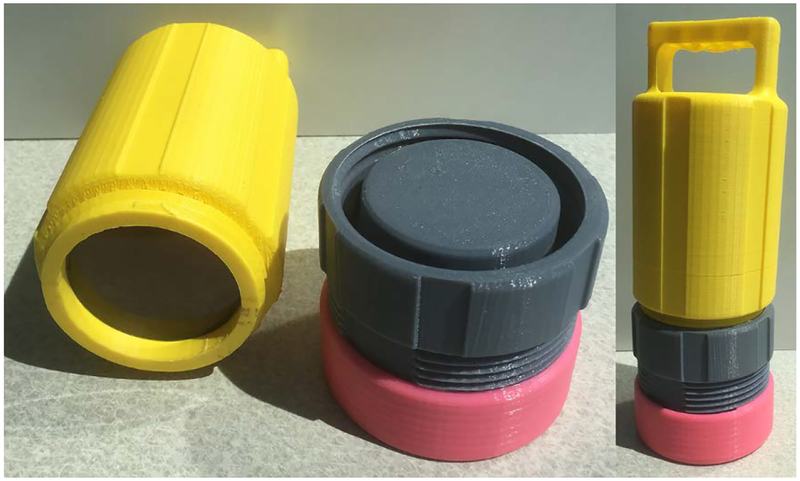
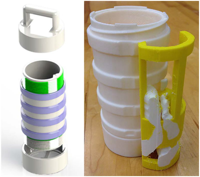
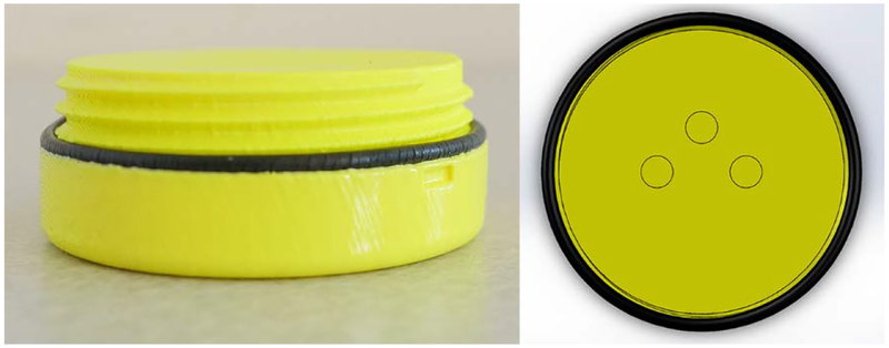
The canister is a thin-wall cylindrical container for the imaging-model and film holder. It has an adjustable screw-on spacer cap at one end for positioning inside the pelvis base. On the other end is a screw-on cap with a pull handle. To minimize friction, yet maintain alignment, contact between the pelvis base and the cartridge is limited to occur on four thin, uniformly-spaced rings. A CAD render and printed prototype are shown in Fig. 9.
Fig 9.
CAD render (left) and printed prototype (right) of the pelvis-base cartridge, version 3. The outer diameter and length of the insert are 5.1 cm and 11.75 cm, respectively.
3.3.2. Combined Imaging-Model and Film Holder.
This holder is the prostate and the intra- and periprostatic structures printed within a frame that can be sectioned in the axial or coronal-sagittal directions to hold film slices. A triangular alignment rail on the inside wall of the canister mates to a triangular notch in the frame. CAD renders and a printed prototype of a single film slice, coronal-sagittal-orientation holder is shown in Fig. 10. Empty space within the canister would be filled with water during use.
Fig. 10.
CAD renders (left) and printed prototypes (right) of the coronal-sagittal combined imaging-model and film holder, version 3
3.4. Pelvis-Base Cartridge, Version 4: Universal Canister with Separate Imaging-Model and Film Holders.
In this version, the approach taken was to separate the imaging-model and the film holder in order to simplify model construction and shorten fabrication time. In this case, positioning the film within the imaging model became the primary concern. Accordingly, a design requirement was specified that the registration tolerance of the film slices with respect to the 3D printed imaging model is less than 0.5 mm.
3.4.1. Universal Canister.
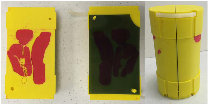
To insure repeatable registration that meets the design requirement, several modifications were made; see Fig. 11. The triangular alignment rail was changed to a dovetail for a tighter fit. The height of the cap was slightly increased so that it compressed an O-ring when screwed into place (see Fig. 11 right). Alignment markings were added to the cap and rim of the canister so the user could tell when the cap was completely screwed on. To further minimize contact friction, the relief slots were changed from circumferential to vertically aligned in the insertion direction. The handle was set flush with the cap and is parallel to the coronal plane when fully closed. Markings were added on to the handle that shows the orientation of the holder inside the canister.
Fig. 11.
CAD images (left, right) and printed prototype (center) of the universal canister, version 4. The O-ring (black, right) is only supported at one location by the backbone of the film holder (gray).
3.4.2. Film Holders.
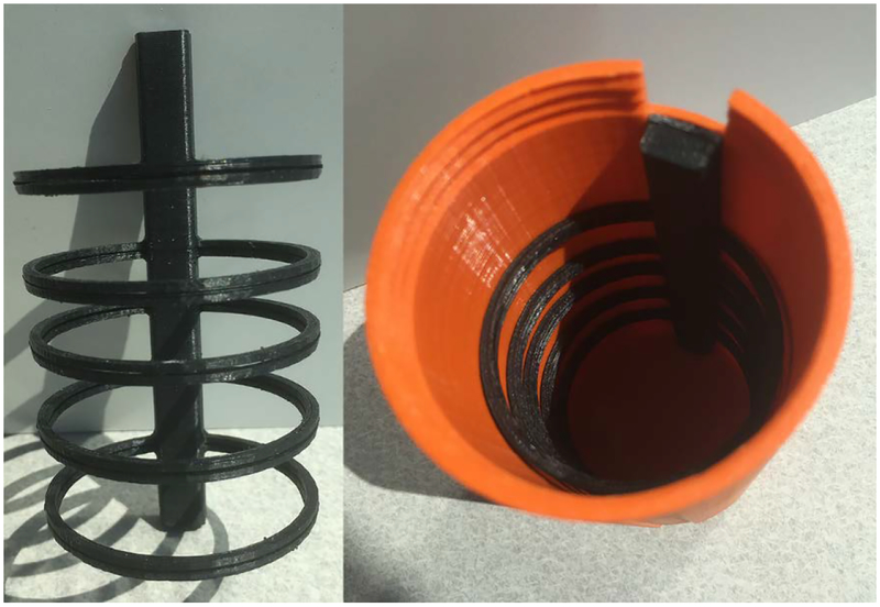
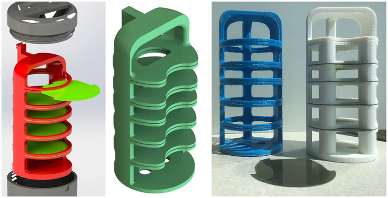
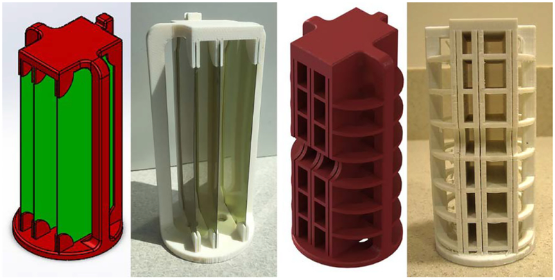
Independent, minimalist frames were designed to hold slices of film. A five-ring axial film holder is shown in Fig. 12. The axially-aligned backbone of the frame dovetails into the canister and has a notch at the top to accommodate the O-ring. A three-slot coronal-sagittal frame is shown in Fig. 13. The number and position of the film rings or slots can be easily adjusted by CAD. The cap leaked due to the lack of compression of the O-ring which is only supported by the holder at one point along its circumference.
Fig 12.
Printed prototype of the axial film holder, version 4. The overall length of the holder is 11.43 cm. The outer diameter of the circular frames is 6.0 cm.
Fig 13.
CAD image (left) and printed prototype (right) of the coronal-sagittal film holder, version 4. The overall height of the holder is 12.54 cm. The diameter of the circular frames is 6.0 cm.
3.4.3. Imaging-Model Holder.
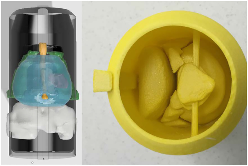
A complementary imaging-model holder was designed in which the anatomical structures were 3D-printed within a thin cylindrical shell with a dovetail rail along the outer wall. Figure 14 shows a CAD render (left) and a printed prototype (right). It was difficult to consistently print imaging-model holders as the D-Limonene used to dissolve the support material absorbed into the walls causing warpage or cracking.
Fig 14.
CAD render (left) and printed prototype (right) f the imaging-model, version 4
3.5. Pelvis-Body Cartridge, Version 5: Iteration of Universal Canister with Separate Imaging-Model and Film Holder.
The changes made for this version were improvements to and expansions of the functionality of Version 4.
3.5.1. Universal Canister.
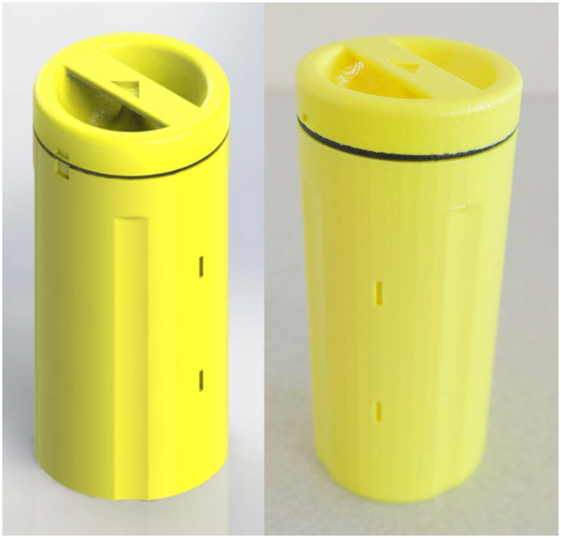
In order to make the canister completely water tight, several modifications were made. The infill of the canister wall was increased to 100%. The fillet along the bottom (closed end) edge was removed. The outside walls of the canister and cap were vapor smoothed (Finishing Touch Smoothing Station, Stratasys Ltd., Eden Prairie, MN); see Fig. 15. Finally, the O-ring was moved from the inside of the canister to the cap; see Fig 16 (left). This position allows uniform pressure to be applied to the O-ring creating proper compression. Repositioning the O-ring also made the assembly of the pelvis-base cartridge easier.
Fig 15.
CAD image (left) and printed prototype (right) of the universal canister, version 5. The outer diameter, wall thickness, and length of the canister body are 6.45 cm, 0.375 cm, and 12.85 cm, respectively. It weighs 106.8 g (100% infill) and takes 7 hours and 45 min to print (alone) on a MakerBot 2×.
Fig 16.
Printed prototype of the universal canister cap, version 5 with O-ring (left). The height of the cap is 2.5 cm. It weighs 66.3 g (100% infill) and takes 4 hrs 27 min to print (alone) on a MakerBot 2×. CAD image of the bottom of the canister showing the three alignment pegs (right).
In the interior, the dovetail was replaced with a rectangular-slotted guide rail that reduced sliding friction yet maintained tight contact. Three alignment pegs (Fig. 16 right) were added to the bottom of the canister. These pegs mated to holes that were added to the bottom of the holders. The asymmetrical pattern insures that there is only a single orientation for the holder inside the canister. Four slots that lie in the center coronal plane were added into the outside wall. Metal dowels (length = 7 mm, diameter = 1.2 mm), epoxied into the slots, are clearly visible in CT scans and serve as fiducial markers for treatment planning.
3.5.2. Film Holder.
During testing, users found it difficult to insert and remove film from version 4 holders because the frames were not sufficiently stiff. Several revisions were created each increasing the amount of material used to stiffen the frame; see Figs. 17–18. The geometry of the film slices and their slots were designed to prevent the film from bending during insertion and to provide a hard stop letting the user feel that the film is fully in-place. The slots were toleranced so that the film could not shift more than 0.5 mm.
Fig 17:
CAD renders (left) and printed prototypes (right) of iterations of axial film holder, version 5. The outer diameter and length of the holders are 5.7 cm and 11.4 cm, respectively.
Fig 18:
CAD renders and printed prototypes of iterations of coronal-sagittal film holder, version 5. The outer diameter and length of the holder are 5.7 cm and 11.7 cm, respectively. The film is 4.44 cm × 10.16 cm.
3.5.3. Imaging-Model Holder.
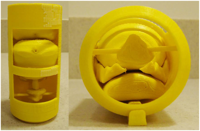
Two changes were implemented to address the swelling and cracking failures of the previous version. The first was to increase the infill percentage of the wall so that it could not absorb solvent. Second, sections were cut out of the frame to give material room to expand. This also resulted in faster printing and more visibility of the interior; see Fig. 19. An alternate version of the holder (shown in Fig. 20) was created in which the prostate and intra- and periprostatic structures were printed separately and then assembled together in a two-part frame. Cut-outs to the frame were placed at points of contact to the anatomical structures. To increase the visibility of boundaries between objects (e.g., DIL, urethra) in CT scans, the number and thickness of surrounding shells were increased.
Fig. 19.
Printed prototype of the imaging model, version 5 which prints as one object. The outer diameter and length are 5.5 cm and 11.4 cm, respectively.
Fig. 20.
Printed prototype of the imaging model, version 5 which prints as separate parts and must be assembled with its frame
3.6. Pelvis-Base Cartridge, Version 6 (Final): Universal Canister with Combined Imaging-Model and Film Holder.
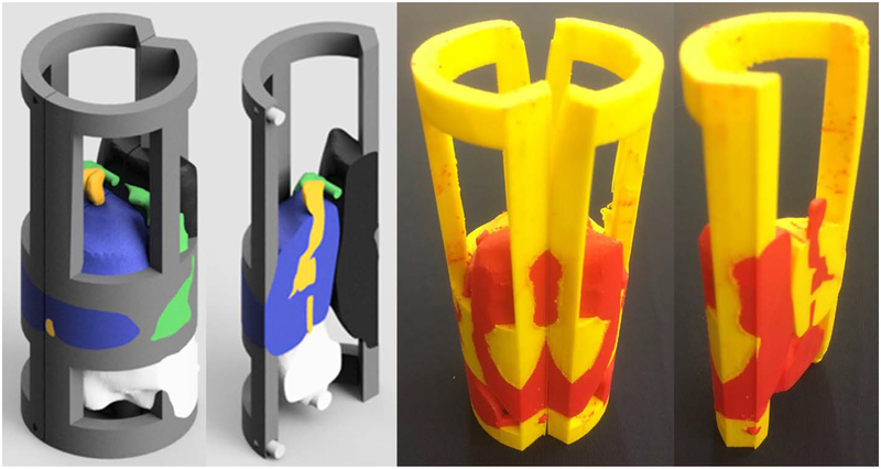
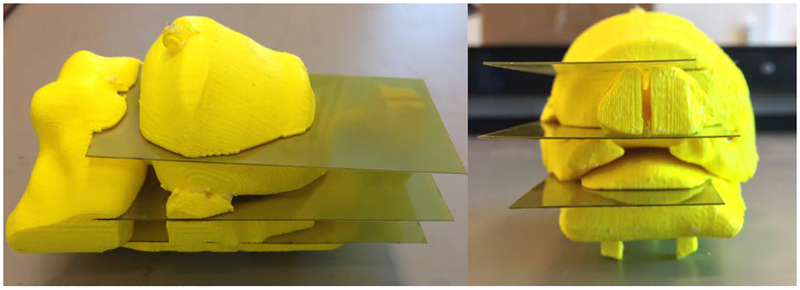
No changes were made to the canister in the final iteration. However, due to concerns that arose during user evaluations of version 5 regarding proper positioning and registration accuracy of the film with respect to the imaging-model, it was decided that the pelvis-base cartridge should return to a combined imaging-model and film holder. In this design, slots for film were directly printed into the imaging model. Figure 21 shows a prototype with three coronal film slots that pass through the rectal wall, the DIL, and prostate gland, respectively. The user knows the film is fully engaged when contact against hard stops is felt. The slots are wide but enough material was left to bear repeated insertion and removal of the film.
Fig. 21.
Printed prototype of the imaging model and film holder, version 6 with coronal slots. The middle slot passes through the centroid of the DIL. The printing time (100% fill) is 7 hours and 47 min.
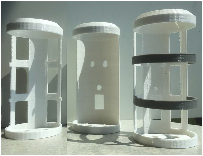
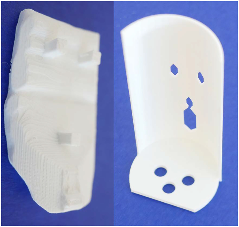
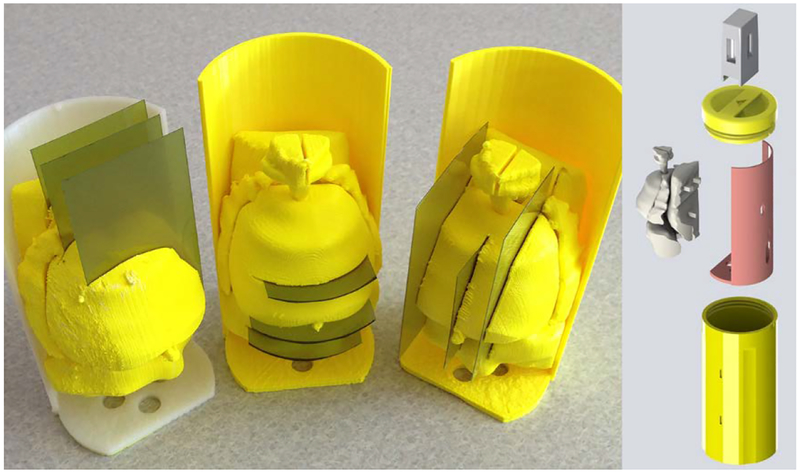
The support frame for the combined imaging-model and film holder went through several iterations. The two primary requirements for the frame are that it be easy to mount and remove the model/holder and that it can be consistently placed in the same position within the canister for each use. Figure 22 shows printed designs for a partially-enclosed cage with end caps, a half-enclosed solid wall with end caps, and a half-enclosed frame with end caps. The final iteration, shown in Fig. 23, has a partial wall with a single end which has the three registration holes that mate to the bottom of the canister. Three square pegs on the back side of the rectal-wall part snap tightly into the frame. Figure 24 (left) shows three mounted prototypes with film slots in the coronal, axial, and sagittal planes, respectively. Figure 24 (right) shows an exploded view CAD render of the holder and canister. An attachment for bubble-level vials can be pressed onto the canister cap handle for orienting the pelvis-base cartridge.
Fig. 22.
Three iterations of printed prototypes of the support frame for the imaging-model and film holder, version 6
Fig. 23.
Final iteration of the support frame (right). Posterior view of rectal wall part with the three square mounting pegs (left).
Fig. 24.
CAD render of pelvis-base cartridge assembly (right). Printed prototypes of coronal, axial, and sagittal-orientation imaging/film holders, version 6 mounted on support frames (left). The holders and their frames weigh 114.6 g, 115.6 g, and 95.0 g, respectively.
4. TREATMENT PLANNING OF RADIATION THERAPY
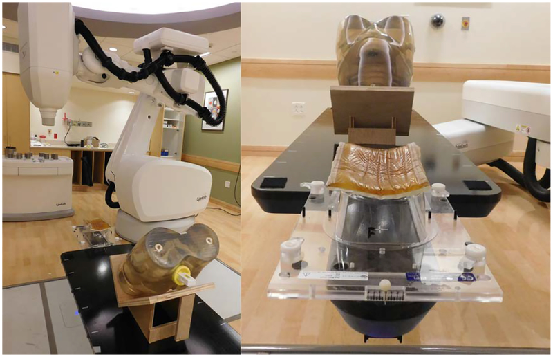
The treatment planning and QA capability of the phantom was demonstrated and evaluated with the CyberKnife System at Boston Medical Center. The CyberKnife is a frameless, image-guided, robotic stereotactic body radiation therapy (SBRT) system. Figure 25 shows the phantom on the six-degree-of-freedom robotic treatment couch. The phantom, which was fitted with the coronal-orientation insert, was set on a wood stand so that the film would lie in a horizontal plane. This allowed the film measurements to be evaluated and directly compared to those from a conventional stereotactic dose verification phantom [23].
Fig 25.
Pelvic phantom on the robotic treatment couch of the CyberKnife System at Boston Medical Center
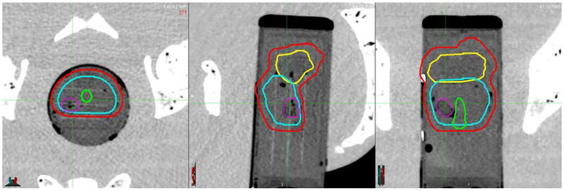
The first step in creating an SBRT treatment plan for a patient is to define the boundaries of the prostate and intra- and periprostatic structures. In CT scans of the phantom taken using the CyberKnife System, relevant clinical structures including the DIL were easily identified and outlined because structural boundaries were clearly distinguishable. Example contours in axial, coronal, and sagittal views, respectively are shown in Fig. 26.
Fig. 26.
CT images (left to right: axial, sagittal, and coronal view) with contours of the PTV (red), seminal vesicles (yellow), urethra (green), prostate gland (cyan), and DIL (purple)
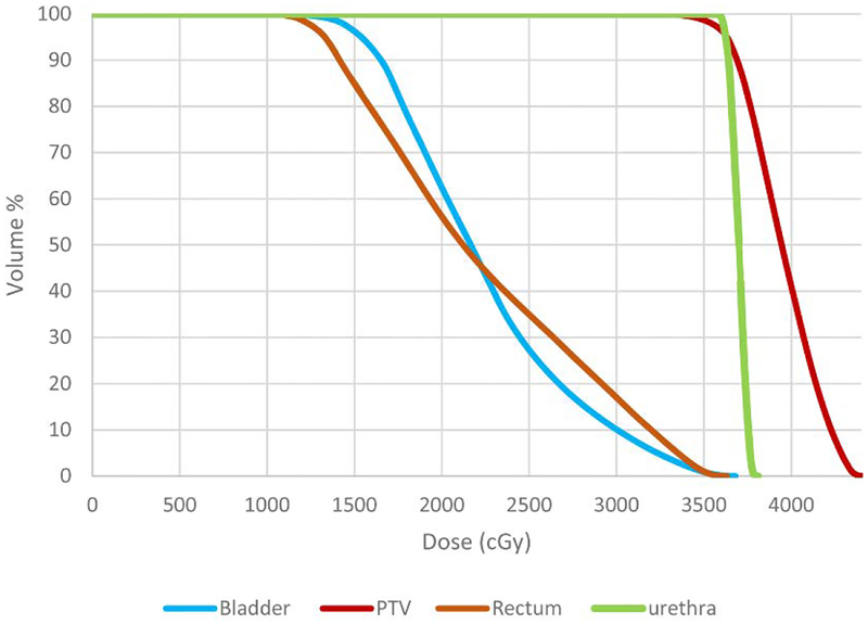
Based on these outlines, a treatment plan was created following the RTOG-0938 protocol (A Randomized Phase II Trial of Hypofractionated Radiotherapy for Favorable Risk Prostate Cancer-RTOG CCOP Study [24]). The protocol calls for a total radiation dose of 36.25 Gy to be delivered to the PTV in five fractions (7.25 Gy per fraction). The dose distribution in relation to the PTV and the selected organs at risk (OAR), rectum, bladder, and urethra, are described in Table 1 and Fig. 27.
Table 1.
Desirable, Limit, and Plan values of the dose, D, delivered to a specified volume and the percent volume, V, delivered a given dose level for the PTV and organs at risk
| PTV | Parameter | Unit | Desirable (>) | Limit (>) | Plan Value |
| D[0.03cm3] | cGy | 4350.0 | 4712.0 | 4416.0 | |
| V [36.25Gy] | % | 95.0 | 90.0 | 95.0 | |
| V [34.4Gy] | % | 100.0 | 99.0 | 99.3 | |
| Organs at Risk | Parameter | Unit | Desirable(<) | ||
| Rectum | D[1cm3] | cGy | 3806.0 | 3574.0 | |
| V [34.4Gy] | % | 3.0 | 2.0 | ||
| V[32.625Gy] | % | 10.0 | 7.8 | ||
| Bladder | D[1cm3] | cGy | 3806.0 | 3600.0 | |
| V[32.625Gy] | % | 10.0 | 7.8 | ||
| Urethra | D[0.03cm3] | cGy | 3878.0 | 3792.0 |
Fig 27.
Cumulative dose volume histogram. The dose bin width is 10 cGy.
Table 1 lists the Desirable, Limit, and Plan values of the dose, D, delivered to a specified volume (in square brackets) and the percent volume, V, delivered a given dose level (in square brackets). For example, the plan specifies that the dose level at the point (defined as having volume 0.03cm3) in the PTV that absorbs the most radiation to be 4416 cGy which falls within the protocol’s Desirable (4350 cGy) and Limit (4712 cGy) values. In terms of percent volume, at least 95% of the PTV will receive a dose of 36.25 Gy. This is greater than the minimum Limit value of 90% and equal to the Desirable value of 95% volume. The plan dosage for the PTV and OAR are presented graphically in the cumulative dose volume histogram (DVH) [25] shown in Fig. 27.
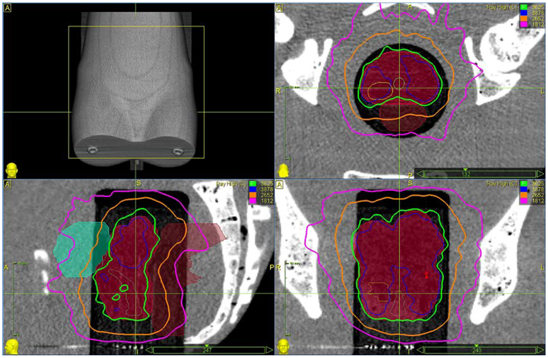
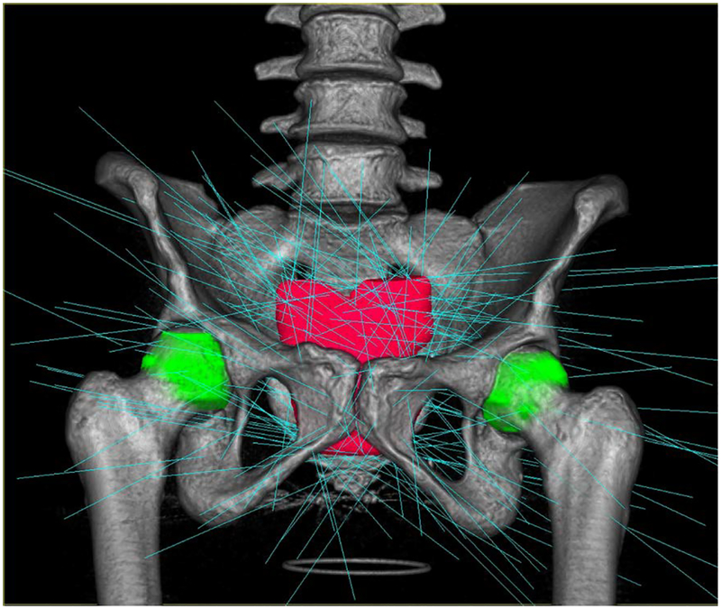
Spatial distribution of the radiation can be illustrated with isodose lines superimposed on a CT image. Figure 28 shows scans in the axial, coronal, and sagittal planes with isodose lines corresponding to 100% (3625 cGy), 107% (3878 cGy), 80% (2652cGy), and 50% (1812cGy) of the prescription dose. The prostate gland is shown in with solid red. Plan calculations call for 209 beam paths which are shown in Fig. 29.
Fig 28.
Example isodose lines in axial (top right), coronal (bottom right), and sagittal (bottom left) planes. The prostate gland is filled in (solid red).
Fig. 29.
Beam paths calculated for the treatment plan
5. QUALITY ASSURANCE OF RADIATION THERAPY
Measurements from radiochromic film (Gafchromic EBT3, Ashland Inc., Covington, KY) incorporated in the phantom were used to quantitatively evaluate the delivered treatment. The EBT3 film is self-developing and changes color when exposed to ionizing radiation. Following a multi-channel dosimetry procedure [26], calibrated film measurements were validated by comparison to known dosages from 100 cGy to 1400 cGy. Measured values for red, green, and blue colors are shown in Table 2. The maximum difference between measured and delivered dose for the highest-point-value of the PTV for a single fraction (4416 cGy/5 fractions = 883.2 cGy) is approximately 2%.
Table 2.
Dose response data for multi-channel, three-color calibration of the dosimetry film
| Known Dose (cGy) | Red | Green | Blue | Average | % Diff |
|---|---|---|---|---|---|
| 100 | 100 | 102.4 | 100.9 | 101.1 | 1.10% |
| 200 | 196.7 | 204.6 | 200 | 200.4 | 0.22% |
| 400 | 393.7 | 403.9 | 398.5 | 398.7 | −0.32% |
| 600 | 600.5 | 607.9 | 604.7 | 604.4 | 0.73% |
| 800 | 817.2 | 818.4 | 817.9 | 817.8 | 2.23% |
| 1000 | 988 | 987 | 987 | 987.3 | −1.27% |
| 1400 | 1406.1 | 1433 | 1433.4 | 1424.2 | 1.73% |
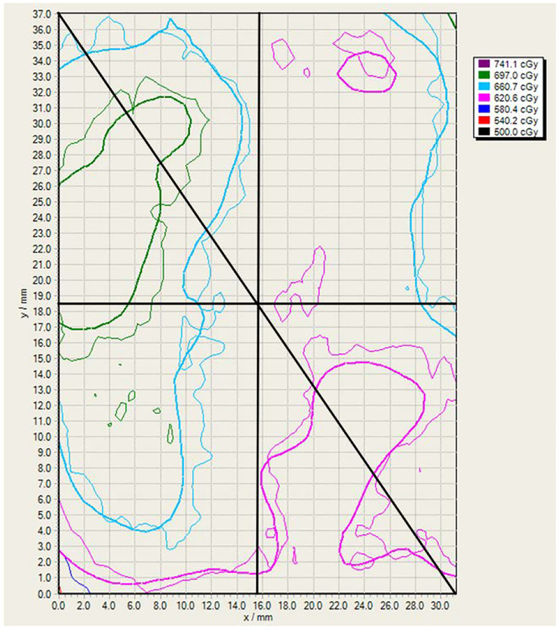
After the CyberKnife system delivered one fraction of the treatment plan, the film was developed and examined using FilmQA Pro Software (Ashland Inc., Covington, KY). Figure 30 is the isodose map of the portion (32.2 mm × 37.1 mm) of the film (superior side) that was contained within the prostate gland in the middle slot (refer to Fig. 21). The delivered and planned dosages correspond to the thick and thin lines, respectively. The contour lines are 500.0, 539.4, 578.7, 618.1, 657.4, 696.8, and 726.1 cGy.
Fig 30.
Isodose map of the film portion within the prostate gland. The delivered and planned dosages correspond to the thick and thin lines, respectively. The contour lines are 500.0, 539.4, 578.7, 618.1, 657.4, 696.8, and 726.1 cGy.
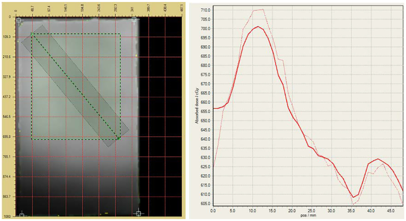
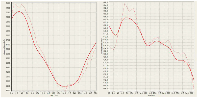
Figure 31 shows the planned (solid) and delivered (dashed) dose profiles (right) along a diagonal line (black, see Fig. 30) from the top left corner to the bottom right corner of the film slice (left). Figure 32 shows the planned (solid) and delivered (dashed) dose profiles corresponding to the horizontal and vertical lines (black, see Fig. 30) that pass through the center of the isodose map, respectively.
Fig 31.
The planned (solid) and delivered (dashed) dose profiles (right) along a diagonal line from the top left corner to the bottom right corner of the film slice (left). The rectangle (green-black dashed) is the outline of the film section corresponding to the isodose map in Fig. 30.
Fig 32.
The planned (solid) and delivered (dashed) dose profiles along the horizontal (left) and vertical (right) lines passing through the center of the isodose map in Fig. 30
Comparison of the delivered dosage to the planned dosage is evaluated using three quantitative measures. The first is the dose differential (DD) which is the percentage difference in dose value at a given point. It is sensitive to sharp gradients but small spatial shifts can result in large difference values. The second is distance to agreement (DTA) which is the distance from a point of reference to the nearest point on the isodose map that has the same value. In shallow gradient regions, large DTA values can arise for small dose differences. The third measure is the gamma (γ) index [27] which combines DD and DTA and is the current prevailing standard. It can be calculated geometrically as the shortest distance between points on surfaces capturing the spatial distribution of the measured and planned dosages and the chosen DD and DTA criteria [28].
The isodose map was discretized into a grid of points or pixels where the size of a pixel is based on the width of the solid line which is taken to be 10 pixels wide. The DD, DTA, and gamma index were calculated for each pixel based on the criteria shown in Table 3. The passing rates of all points on the map are listed, e.g., 99.8% of the points meet the gamma index passing criterion. These results indicate clear validation of the delivered dosage with respect to the planned dosage.
Table 3.
Summary of the dose differential, distance to agreement, and gamma index calculations for the isodose map (Fig. 30). Pixel size is based upon the width of the solid lines and taken to be 10 pixels.
| Dose Differential | Distance to Agreement | Gamma | |
|---|---|---|---|
| Criterion | |2.0%| | 2.0%, 2.0 mm | 2.0%, 2.0 mm |
| Passing Rate | 86.7% | 100.0% | 99.8% |
| Failing Rate | −6.1, +7.2% | −0.0, +0.0% | −0.0, +0.2% |
| Mean | 1.1% | 0.2% | 0.8% |
| Std. Dev. | 0.9% | 0.4% | 0.4% |
6. CONCLUSION
A novel pelvic phantom containing a patient and organ-specific, 3D printed model created from the MR images of a patient has been designed, fabricated, and tested. It combines the high-resolution detail of MR imaging and CT-based planning without the need for direct image integration. This phantom can be used to design and optimize treatment for the given patient using current EBRT systems. Furthermore, the phantom also has the capability to perform radiation dosage QA. The process to fabricate the phantom presented herein can be carried out with current commercial systems and directly translated into practice.
Results from treatment planning, delivery, and QA with the phantom by the CyberKnife System at Boston Medical Center demonstrate that the phantom can be successfully employed in a clinical setting. Users found the phantom intuitive and simple to operate, that it met the design goals of being easy to adapt to multiple patients, quick to fabricate, simple to deploy, and that its measurements were repeatable. In terms of enabling new research, this phantom is also a convenient platform on which to develop and evaluate novel MR-imaging-based external beam radiation therapies.
ACKNOWLEDGEMENT
The authors gratefully acknowledge the work done by Lindsey Andrade, Tatiana Anthony, Myles Cooper, Jeffery Pflueger, Elena Shaw, and Kevin Suzuki on the design and fabrication of early versions of the phantom; and by Helen Lyons on the initial CAD model.
FUNDING
CL, MD, UD, and AD were funded in part by the Olin College Intellectual Vitality Program and by the MA Space Grant Consortium.
REFERENCES
- [1].Hoskin Peter, Ed., 2012, External Beam Therapy, 2nd ed Oxford University Press, Oxford, UK: ISBN-13: 978–0199696567 [Google Scholar]
- [2].Podgorsak EB, Ed., 2005, Radiation Oncology Physics: A Handbook for Teachers and Students, IAEA, Vienna, Austria: ISBN 92–0–107304–6 [Google Scholar]
- [3].Schmidt MA, and Payne GS, 2015, “Radiotherapy Planning using MRI.” Phys. Med. Biol, 60, (22), pp. R323–361. DOI: 10.1088/0031-9155/60/22/R323 [DOI] [PMC free article] [PubMed] [Google Scholar]
- [4].Dowling JA, Lambert J, Parker J, Salvado O, Fripp J, Capp A, Wratten C, Denham JW, and Greer PB, 2012, “An Atlas-Based Electron Density Mapping Method for Magnetic Resonance Imaging (MRI)-Alone Treatment Planning and Adaptive MRI-Based Prostate Radiation Therapy.” Int. J. Radiat. Oncol. Biol. Phys, 83(1), pp. e5–e11. DOI: 10.1016/j.ijrobp.2011.11.056 [DOI] [PubMed] [Google Scholar]
- [5].Paliwal BR, Ritter MA, McNutt TR, Mackie TR, Thomadsen BR, Purdy JA, and Kinsella TJ, 1998, “A Solid Water Pelvic and Prostate Phantom for Imaging, Volume Rendering, Treatment Planning, and Dosimetry for an RTOG Multi-Institutional, 3-D Does Escalation Study.” Int. J. Radiat. Oncol. Biol. Phys, 42(1), pp. 205–211. DOI: 10.1016/S0360-3016(98)00187-4 [DOI] [PubMed] [Google Scholar]
- [6].Followill DS, Evans DR, Cherry C, Molineu A, Fisher G, Hanson WF, and Ibbott GS, 2007, “Design, Development, and Implementation of the Radiological Physics Center’s Pelvis and Thorax Anthropomorphic Quality Assurance Phantoms,” Med. Phys, 34(6), pp. 2070–2076. DOI: 10.1118/1.2737158 [DOI] [PubMed] [Google Scholar]
- [7].Harrison KM, Ebert MA, Kron T, Howlett SJ, Cornes D, Hamilton CS, and Denham DW, 2011, “Design, Manufacture, and Evaluation of an Anthropomorphic Pelvic Phantom Purpose-Built for Radiotherapy Dosimetric Intercomparison.” Med. Phys, 38 (10), pp. 5330–5337. DOI: 10.1118/1.3626573 [DOI] [PubMed] [Google Scholar]
- [8].Meakin JR, Shepherd DET, and Hukins DWL, 2009, “Fused Deposition Models from CT Scans,” Br. J. Radiol, 77, pp. 504–507. DOI: 10.1259/bjr/50012454 [DOI] [PubMed] [Google Scholar]
- [9].Reniger F, Mehndiratta A, von Tengg-Kobligk H, Zechmann CM, Unterhinninghofen R, Kauczor H-U, Giesel FL, 2010, “3D Printing Based on Imaging Data: Review of Medical Applications.” Int. J. Comput. Assist. Radiol. Surg, 5, pp. 335–341. DOI: 10.1007/s11548-010-0476-x [DOI] [PubMed] [Google Scholar]
- [10].Breseman K, Lee CL, Bloch BN, and Jaffe CC, 2013, “Constructing 3D-Printable CAD Models of Prostates from MR Images,” Proc. 2013 39th Annual Northeast Bioengineering Conference, Syracuse, NY, pp. 27–28. DOI: 10.1109/NEBEC.2013.8 [DOI] [Google Scholar]
- [11].Kumar R, Sharma SD, Despande S, Ghadi Y, Shaiju VS, Amols HI, and Mayya YS, 2010, “Acrylonitrile Butadiene Styrene (ABS) Plastic-Based Low Cost Tissue Equivalent Phantom for Verification Dosimetry in IMRT.” J. Appl. Clin. Med. Phys, 11(2), pp. 24–32. DOI: 10.1120/jacmp.v11i1.3030 [DOI] [PMC free article] [PubMed] [Google Scholar]
- [12].Trivedi H, Turkbey B, Rastinehad AR, Benjamin CJ, Bernardo M, Pohida T, Shah V, Merino MJ, Wood BJ, Linehan WM, Venkatesan AM, Choyke PL, and Pinto PA, 2012, “Use of Patient-Specific MRI-Based Prostate Mold for Validation of Multparametric MRI in Localization of Prostate Cancer.” Urology, 79(1), pp. 233–239. DOI: 10.1016/j.urology.2011.10.002 [DOI] [PMC free article] [PubMed] [Google Scholar]
- [13].Leary M, Kron T, Keller C, Franich R, Lonshi P, Subic A, and Brandt M, 2015, “Additive Manufacture of Custom Radiation Dosimetry Phantoms: An Automated Method Compatible with Commercial Polymer 3D Printers,” Mater. Des, 86, pp. 487–499. DOI: 10.1016/j.matdes.2015.07.052 [DOI] [Google Scholar]
- [14].Madamesila J, McGeachy P, Eduardo Villarreal Barajas J, Khan R, 2016, “Characterizing 3D Printing in the Fabrication of Variable Density Phantoms for Quality Assurance of Radiotherapy,” Phys. Med, 32, pp. 242–247. DOI: 10.1016/j.ejmp.2015.09.013 [DOI] [PubMed] [Google Scholar]
- [15].Ehler ED, Barney BM, Higgins PD, and Dusenbery KE, 2014, “Patient Specific 3D Printed Phantom for IMRT Quality Assurance.” Phys. Med. Biol, 59, pp. 5763–5773. DOI: 10.1088/0031-9155/59/19/5763 [DOI] [PubMed] [Google Scholar]
- [16].Bloch BN, Jain A, and Jaffe CC, 2015. Data from PROSTATE-DIAGNOSIS. The Cancer Imaging Archive, accessed 1/18/18, 10.7937/K9/TCIA.2015.FOQEUJVT [DOI]
- [17].Clark K, Vendt B, Smith K, Freymann J, Kirby J, Koppel P, Moore S, Phillips S, Maffitt D, Pringle M, Tarbox L, Prior F., 2013, “The Cancer Imaging Archive (TCIA): Maintaining and Operating a Public Information Repository.” J Digit. Imaging, 26(6), pp 1045–1057. DOI: 10.1007/s10278-013-9622-7 [DOI] [PMC free article] [PubMed] [Google Scholar]
- [18].Fedorov A, Beichel R, Kalpathy-Cramer J, Finet J, Fillion-Robin J-C, Pujol S, Bauer C, Jennings D, Fennessy FM, Sonka M, Buatti J, Aylward SR, Miller JV, Pieper S, Kikinis R, 2012, “3D Slicer as an Image Computing Platform for the Quantitative Imaging Network.” Magn. Reson. Imaging 30(9), pp. 1323–41. DOI: 10.1016/j.mri.2012.05.001 [DOI] [PMC free article] [PubMed] [Google Scholar]
- [19].“Seg3D: Volumetric Image Segmentation and Visualization,” Scientific Computing and Imaging, accessed 1/18/18, http://www.seg3d.org.
- [20].“Blender-a 3D modelling and rendering package,” Blender Online Community, Blender Foundation, accessed 1/18/18, http://www.blender.org.
- [21].Ross C, Donlon E, Kessler A, Lee C, Xiang H, Jaffe CC, and Bloch BN, 2015, “Patient and Organ Specific Quality Assurance Phantom Insert for Stereotactic Body Radiation Therapy of Prostate Cancer,” J. Med. Device, 9(2), pp. 020938–1– 2 DOI: 10.1115/1.4030146 [DOI] [Google Scholar]
- [22].Heyns M, Breseman K, Lee CL, Bloch BN, Jaffe C, and Xiang H, 2013, “Design of a Patient-Specific Radiotherapy Treatment Target,” Proc. 2013 39th Annual Northeast Bioengineering Conference, Syracuse, NY, pp. 171–172. DOI: 10.1109/NEBEC.2013.75 [DOI] [Google Scholar]
- [23].Alshammari M, 2016, “Treatment Planning and Dosimetric Verification of Cyberknife Prostate SBRT (Sterotatic Body Radiation Therapy) on an MR-Based 3D Prostate Model Imaging Insert in a Pelvis Phantom,” M.S. thesis, Boston University School of Medicine, Boston, MA: http://open.bu.edu/handle/2144/16805 [Google Scholar]
- [24].RTOG-0938 Protocol Information. A Randomized Phase II Trial of Hypofractionated Radiotherapy for Favorable Risk Prostate Cancer-RTOG CCOP Study, current version 5/20/16, accessed 1/18/18, https://www.rtog.org/ClinicalTrials/ProtocolTable/StudyDetails.aspx?study=0938
- [25].Drzymala RE, Mohan R, Brewster L, Chu J, Goitein M, Harms W, and Urie M, 1991, “Dose-Volume Histograms,” Int. J. Radiat. Oncol. Biol. Phys, 21(1), pp. 71–17. DOI: 10.1016/0360-3016(91)90168-4 [DOI] [PubMed] [Google Scholar]
- [26].Micke A, Lewis DF, and Yu X, 2011, “Multichannel Film Dosimetry with Nonuniformity Correction,” Med. Phys, 38(5), pp. 2523–2534. DOI: 10.1118/1.3576105 [DOI] [PubMed] [Google Scholar]
- [27].Low DA, Harms WB, Mutic S and Purdy JA, 1997, “A Technique for the Quantitative Evaluation of Dose Distributions,” Med. Phys, 25(5), pp. 656–661. DOI: 10.1118/1.598248 [DOI] [PubMed] [Google Scholar]
- [28].Ju T, Simpson T, Deasy JO, and Low DA, 2008, “Geometric Interpretation of the g Dose Distribution Comparison Technique: Interpolation-Free Calculation,” Med. Phys, 35(3), pp. 879–887. DOI: 10.1118/1.2836952 [DOI] [PubMed] [Google Scholar]


