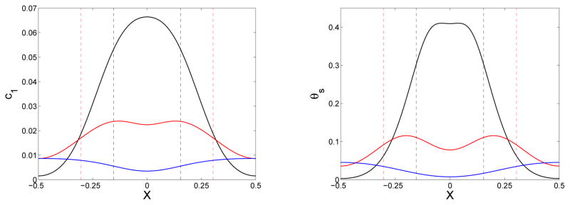
Figure 8.
Plots of c1(x, t) (left) and θs(x, t) (right) at t = 0.5 (black), 1.0 (red), and 2.5 (blue).Note the reversal of the slope of the c1 and θs curves at later times. Dashed lines indicate location of gel front at t = 0.5 (black) and t = 1.0 (red). The gel front has reached x = 0.5 by t = 2.5. The simulations start with c1(x, 0) given by Eq. (45) with ε = 0.1 and Si = 1. D = D1 = 0.02.

