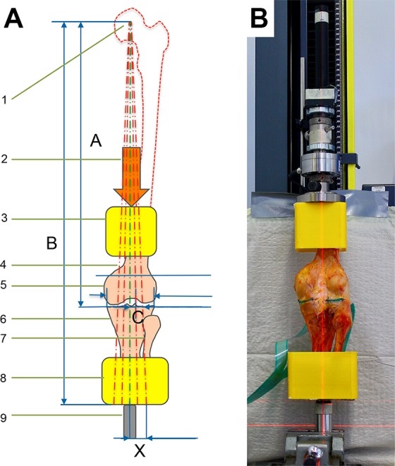
Figure 1.

(A) Overview of the biomechanical alignment and compression setup (not to scale), consisting of (1) the center point of the femoral head, (2) the direction of the applied force, (3, 8) specimen potting, (4) laser projections for varus/neutral/valgus, (5) the distal femur, (6, 7) the proximal tibia and fibula, and (9) the ball bearing that can be shifted to meet the corresponding laser line. The amount of medial and lateral translation of the tibial fixation cap was calculated as: X = (B/A) × C. (B) Photograph depicting the virtual femoral head 50 cm above the joint line and the approximate 6° offset of the femoral anatomic axis to the potting casts. The neutral mechanical axis was defined as a strictly vertical connection between the center of the femoral head, the center of the tibial plateau, and the tibial ball bearing. Perpendicular laser lines imitating the Mikulicz line and the joint line monitored the medial and lateral shifts of the tibial fixation cap.
