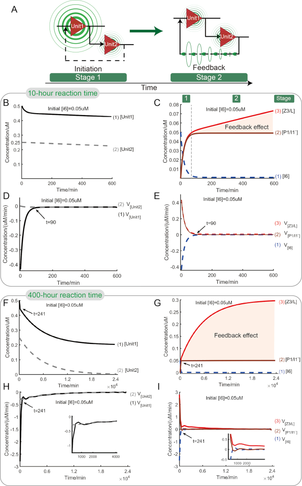
Figure 6.
Simulative analysis for feedback circuit. (A) Illustration of stage evolution of circuit. (B) Time-dependent changes of concentrations of reactants, Unit1 and Unit2, during 10-h reaction process. (C) Time-dependent changes of concentrations of reactants, input strand I6, linker strand P1/I1′ and output complex Z3/L, during 10-h reaction process. Reaction stage was labeled on the top of the figure. The shaded area demonstrates the feedback effect of Unit2 to Unti1 in 10-h reaction process. (D) Time-dependent changes of reaction rates of reactants, logic units Unit1 and Unit2, during 10-h reaction process. (E) Time-dependent changes of reaction rates of reactants, input strand I6, linker strand P1/I1′ and output strand Z3/L, during 10-h reaction process. (F)–(I) present asymptotic analysis for the feedback circuit. (F) Time-dependent changes of concentrations of reactants, Unit1 and Unit2, during 400-h reaction process. (G) Time-dependent changes of concentrations of reactants, input strand I6, linker strand P1/I1′ and output complex Z3/L, during 400-h reaction process. The shaded area demonstrates the feedback effect of Unit2 to Unti1 in 400-h reaction process. (H) Time-dependent changes of reaction rates of reactants, Unit1 and Unit2, during 400-h reaction process. (I) Time-dependent changes of reaction rates of reactants, input strand I6, linker strand P1/I1′ and output strand Z3/L, during 400-h reaction process.

