Figure 6.
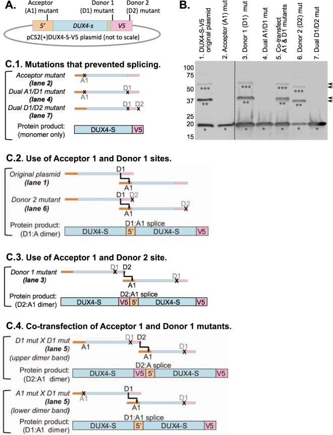
Confirmation of acceptor and donor splice sites. (A) Diagram of DUX4-S-V5 plasmid showing approximate locations of acceptor (A1) and donor site (D1, D2) mutations (see Fig. 5 for details). (B) Immunoblot of V5-tagged proteins produced 48 h after transfection of HEK293 cells. Apparent monomers, dimers, and trimers are indicated by single, double, and triple asterisks respectively. No apparent multimers were generated when a single plasmid was transfected in which either (i) the acceptor site (lane 2), (ii) both the acceptor and donor 1 sites (lane 4), or (iii) both donor sites (lane 7) were mutated. Multimers were generated, however, when only one of the donor sites was mutated (lane 3, D1; and lane 6; D2), but the multimers generated when the D1 site was mutated were larger in size (arrows) as expected if the D2 site was used when the D1 site was disabled. When two separate plasmids were co-transfected (lane 5), one with the acceptor mutation and one with the donor 1 mutation, multimers were formed as expected for trans-splicing. (C) Diagram of trans-splicing patterns underlying the immunoblot results in panel B. In each diagram, the mRNAs are pictured schematically with the 5′ region in light orange, the DUX4-S coding sequence in light blue, and the V5 epitope in light red. Functional acceptor (A1) and donor (D1, D2) sites are indicated with black lettering, whereas mutated sites are indicated with gray lettering and an “X.” For each diagram, the corresponding lane of the immunoblot in panel B is indicated. Note that for lane 5 (C.4, Co-transfection of Acceptor 1 and Donor 1 mutants), two dimers of different sizes are possible and, indeed, two dimer bands are seen in lane 5 of panel B, though the smaller band is fainter than the larger band.

