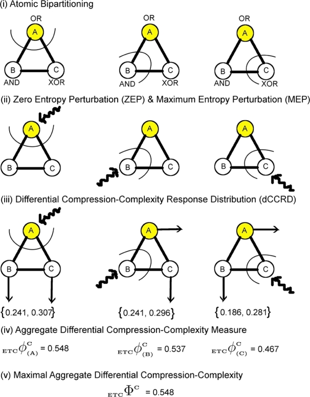
Figure 7.

Algorithm for the computation of ΦC is illustrated through diagrams. The network ABC (current state = (1,0,0)) constitutes three logic gates: OR, AND, XOR for which the value of ΦC is computed. (i) The network is partitioned into 3 possible atomic bipartitions, (ii) each atomic bipartition is perturbed with a Maximum Entropy Perturbation (MEP) which is a random input binary time series (length = 200) as well as Zero Entropy Perturbation (ZEP) which is a constant sequence (length = 200), (iii) Differential Compression-Complexity is computed by taking the difference between complexities for MEP and ZEP for each output time series from the remaining two unperturbed nodes. This forms the Differential Compression-Complexity Response Distribution (dCCRD) for each bipartition. For example,  ,
,  , represents the dCCRD of the time series obtained from the nodes B and C respectively, when the node A is perturbed. Similarly, the dCCRD for the other two bipartitions are:
  ,
,  and
and  ,
,  , (iv) the individual values of each dCCRD are summed up to obtain ‘Aggregate Differential Compression-Complexity Measure’ for each bipartitioned-perturbed network. Therefore,
  and similarly
  and
and  can be computed. All corresponding values are:
  ,
,  ,
,  , (v) Maximal-Aggregate Differential Compression-Complexity, ΦC, is nothing but the maximum of the Aggregate Differential Compression-Complexity measures:
  . Thus,
  . For more details, please refer to ‘Supplementary Text’.
