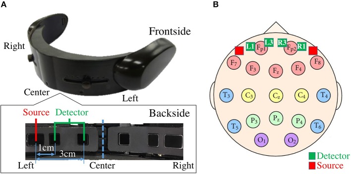
Figure 1.
(A) fNIRS device in present study. Bottom subplot on left shows arrangement of source-detector of four channels of this device. Distances between short (i.e., 1.0 cm) and long (i.e., 3.0 cm) source and detector of left and right channels are shown. (B) Arrangement of 10–20 International Standard System: In this figure, relative locations of channels of fNIRS device in our study (i.e., L1, L3, R1, and R3) are depicted in red (i.e., sources) and green (i.e., detectors) squares. L1, R1, L3, and R3 are channels with short (i.e., 1.0 cm) and long (i.e., 3.0 cm) source-detector distances.

