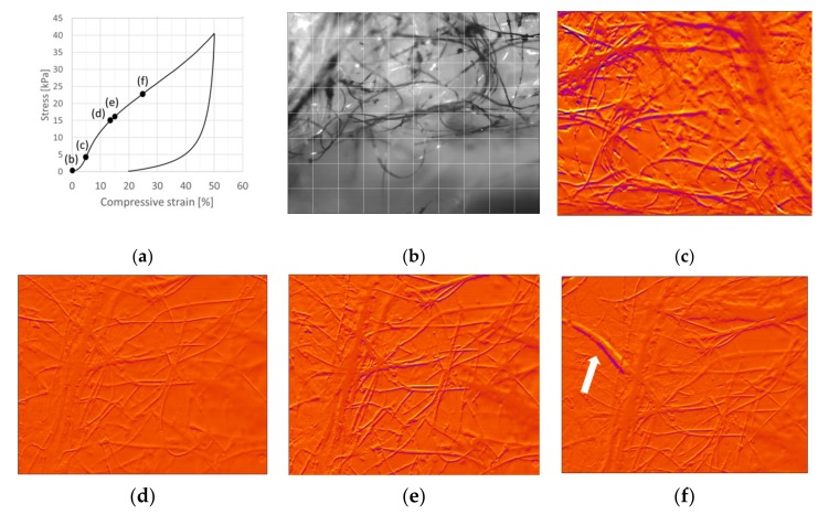
Figure 9.
Compression test of the viscose sample V9. (a) Stress–strain curve for a 50% compression cycle. (b) Image of the network at 0% compression. Correlation plots showing dislocations of fibers from previous locations (shown in yellow color) to new adjacent locations (shown in dark purple color). (c) Intense and large dislocations in the network at 4.6%. (d) The network showing moderate and evenly distributed dislocations at 13.5% compression. (e) After 0.8 s at 14.5% compression, the dislocations intensified again. (f) An abrupt large fiber dislocation at 25.1% compression. Imaging frequency: 10 Hz.

