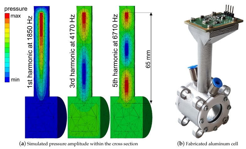
Figure 3.
(a) Cross section of the cell with simulated pressure amplitude corresponding to standing wave patterns of different harmonics. One can observe the first harmonic at 1850 Hz, the third harmonic at 4170 Hz and the fifth at 6710 Hz. Pressure peaks (red) are at the spot, where the microphone will be assembled. As expected, no standing wave pattern is formed within the absorption chamber. (b) Picture of the aluminum cell with mounted microphone and windows (100 mm × 40 mm × 40 mm).

