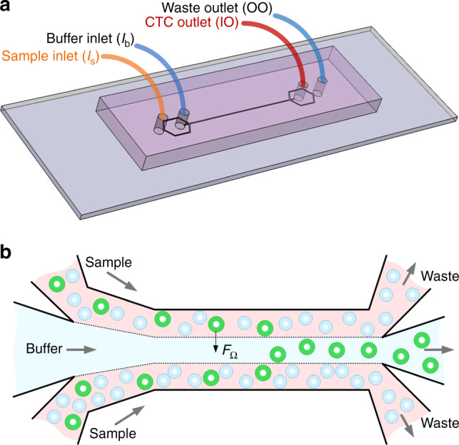
Fig. 1. Device layout and schematic illustrating the working principle of inertial migration.

a Configuration of the inlets and outlets. Blood sample and PBS buffer are introduced into the channel from sample inlet (Is) and buffer inlet (Ib), forming the sandwiched flow configuration in the main channel as shown in (b). CTCs are separated and collected from the inner outlet (IO) and other blood cells smaller than the cutoff size are collected from the outer outlet (OO). b Topview of the multi-flow configuration enabling the size-dependent differential migration of cells toward buffer flow in the middle of the main channel. One of the main inertial forces, rotation-induced lift force (FΩ), is the predominant force behind the size-based lateral migration and subsequent isolation of target circulating tumor cells (CTCs) in this device
