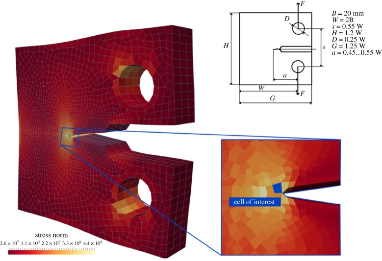
Figure 8.
The standard ASTM ‘compact-tension’ test set-up dimensions (top, right); vertical eccentric pulling of the holes generates a tensile mechanical state localized in the notch tip as illustrated by the stress field (∥σ∥); the mesh of the continuum model (in blue, left) is refined in the vicinity of the notch tip; the blue-filled cell (bottom, right) is used for the detailed mechanical analysis in figure 9. (Online version in colour.)

