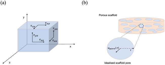
Figure 4.
(a) A 3D graphical representation of the shear stresses, exemplified on the sides of a box, which are used to calculate the wall shear stress (equations (7) and (8)); (b) an example of an idealised perfectly circular pore, which is used to calculate the velocity inside the pore and subsequently the wall shear stress exerted on the pore walls (equations (9)–(11)).

