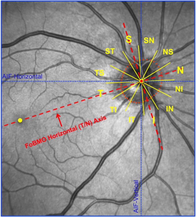
Figure 4.

FoBMO 30° ONH sectors for a representative study eye (FDA056). The fovea (yellow dot) and four BMO points were anatomically identified using real-time OCT imaging at the time of image acquisition by the technician. The delineated BMO points from the 24 acquired OCT B-scans are projected onto the IR image along with the geometric center of BMO (BMO centroid - red dot with yellow border) so as to establish the foveal to BMO (FoBMO) axis. Twelve 30° (clock-hour) sectors were then established relative to the FoBMO axis. Note that the use of the FoBMO axis for orientation rather than the acquired image frame vertical and horizontal axes (blue dotted lines) means that the 12 FoBMO sectors were applied in an anatomically consistent fashion to each study eye.24,26,58 S, superior; SN, superior nasal; NS, nasal superior; N, nasal; NI, nasal inferior; IN, inferior nasal; I, inferior; IT, inferior temporal; TI, temporal inferior; T, temporal; TS, temporal superior; ST, superior temporal.
