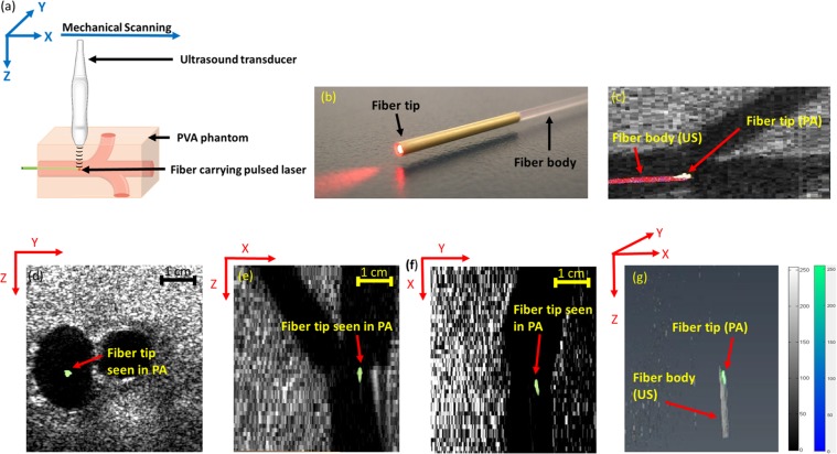
Figure 2.
(a) Experimental setup for straight fiber tip tracking. (b) image showing the ablation fiber used, the ablation fiber has a gold covering at its tip. (c) Fiber tip seen using PA imaging, body of the fiber seen using US imaging. Appearance of the straight fiber in combined US and thresholded PA imaging in (d) transverse, (e) sagittal, and (f) coronal planes. (g) Volumetric image of the fiber in both US and thresholded PA images indicating that PA is only visualizing the fiber tip while US imaging shows the whole fiber body. Supplementary Movie 1 shows the volumetric US and PA of the phantom with straight fiber.

