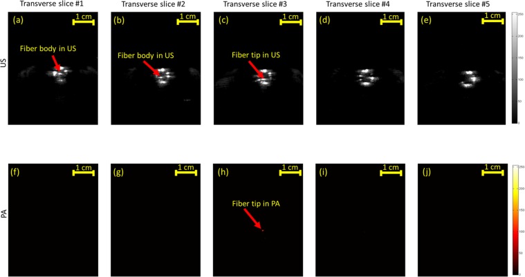
Figure 6.
US (a–e) and PA (f–j) mechanically scanned transverse images of a fiber tip placed inside a blood-filled tube at behind (panels a–b and f–g) of the tip, at the fiber tip (panels c,h) and after passing the fiber (panels d–e, and i–j). US imaging is unable to distinguish between the fiber tip and the cross section of the fiber in (a–c). The accurate location of the fiber tip is clearly seen using thresholded PA imaging in (h).

