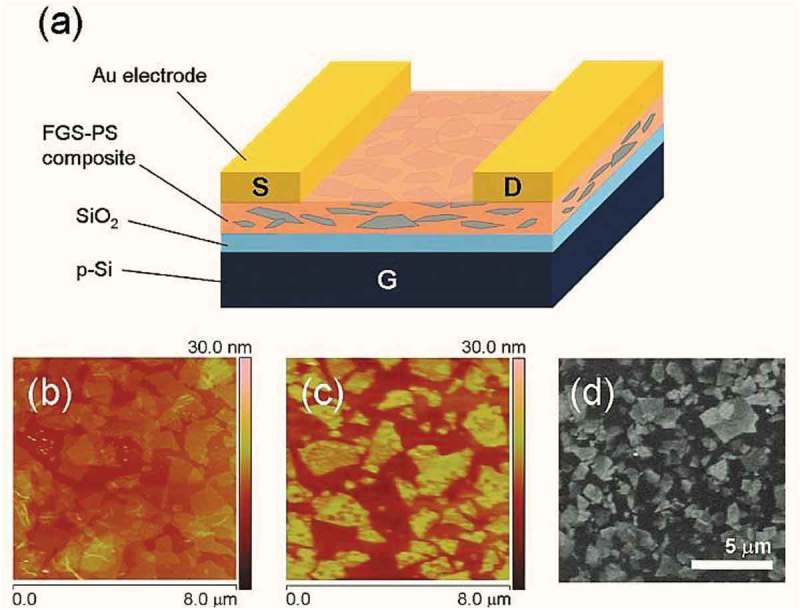
Figure 17.

(a) Thin film of FGS-PS composite diagram. AFM of (b) phenyl-isocyanate treated GO and (c) thin film of FGS-PS composite. (d) SEM of typical FGS-PS composite thin film as-deposited. Contrast can be realized between conductive FGS (light) and insulating PS (dark) (adapted from reference [188]).
