Figure 7.
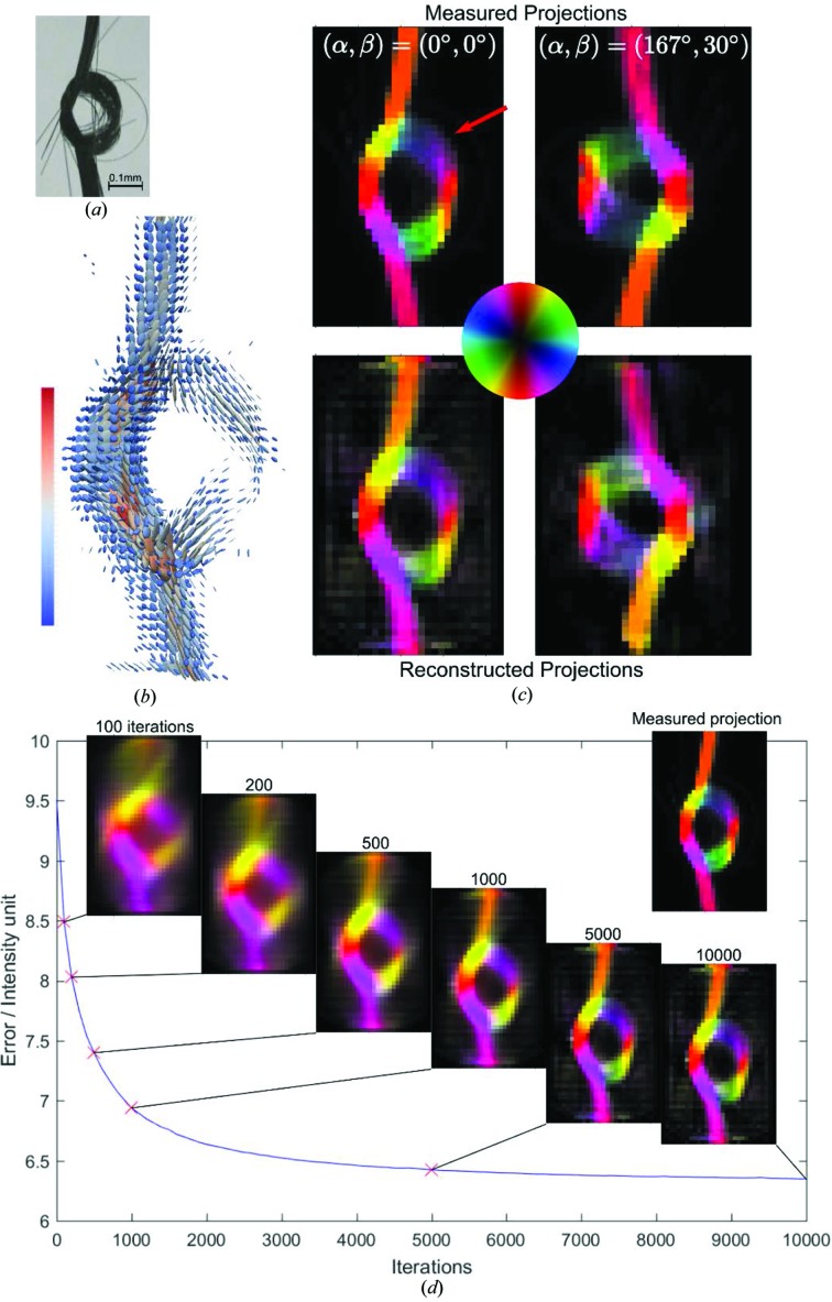
IRTT reconstruction of the carbon fiber knot. (a) Optical image of the fiber knot, where regions of loose fiber packing are visible. (b) Results of the tensor reconstruction visualized as 3D ellipsoids. The color bar indicates the tensor magnitude in linear scale and arbitrary units. (c) Experimental and IRTT-derived orientation-encoded maps are shown in the upper and lower panels, respectively, for two sample orientations. The red arrow points to a region of loosened fibers. Orientation is color-coded by the color wheel. (d) Error evolution versus iteration number, and orientation-encoded reconstructed projections for selected iteration numbers. The measured projection is also shown as an inset.

