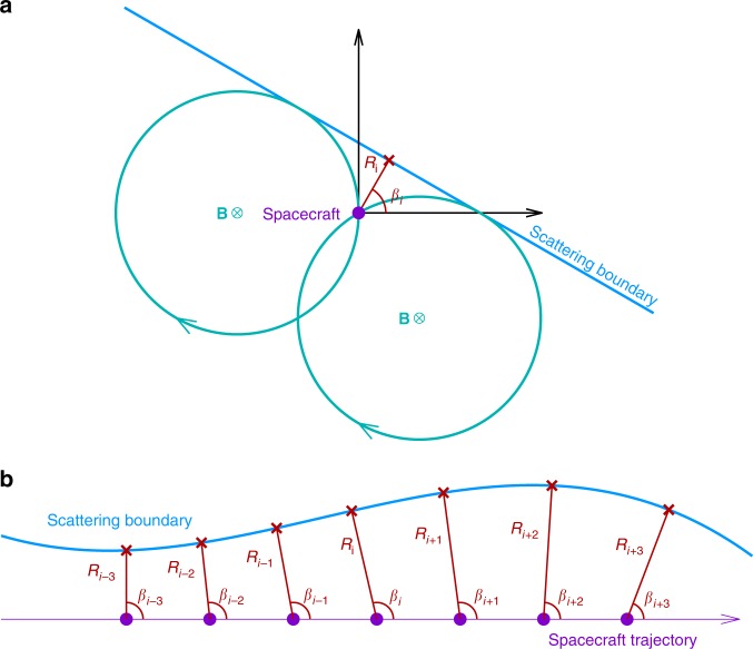
Fig. 7.
Schematic diagram of the energetic particle sounding technique. In panel a a spacecraft (purple dot) is located near a scattering boundary. In the plane perpendicular to the magnetic field, the particle detector needs to collect electrons from all directions to get a full perpendicular PSD (PSD⊥). However, the measured PSD⊥ is not gyrotropic because electrons outside the boundary can be scattered away by the boundary. Two critical looking directions (ϕ1 and ϕ2), corresponding to the gyro-orbits tangential to the boundary (two cyan circles), can be recognized by sharp PSD declines. The two critical directions as well as the particle gyro-radius can be used to calculate the boundary orientation (βi) and distance (Ri) to the spacecraft. Panel b shows an example of boundary sounding. Using PSD⊥ data for a certain energy channel, the sounding technique generates a data point (red) at each moment, leading to a series of orientations (βi−3,…, βi + 3) and distances (Ri−3,…, Ri+3) throughout the whole traversal. The corresponding data points (red crosses) are obtained based on the known spacecraft location. The boundary geometry can be obtained by connecting these points

