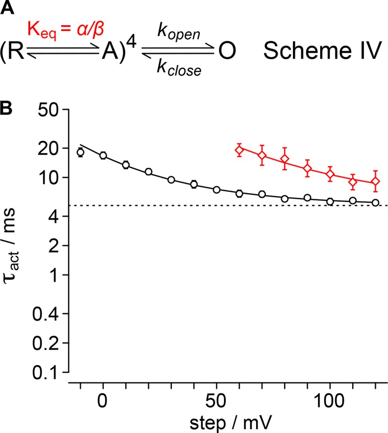
Figure 10.

Voltage sensor equilibrium gating scheme. (A) Gating scheme in which τact is determined by the probability that voltages sensors are in their activated state. Activation of four identical resting voltage sensors is determined by the α/β equilibrium. Pore opening is a voltage-independent concerted event with rate kopen and reverse rate kclose. Equilibrium susceptible to GxTx is red. (B) Fit of Eq. 9 to τact from Fig. 2 C. Dashed line, (kopen + kclose)−1 = 5.1 ± 0.1 ms; black solid line, vehicle; = 0.33 ± 0.01, z = 0.61 ± 0.06 e0; red solid line, 1 µM GxTx, = 1.2 ± 0.2, z = 0.45 ± 0.04 e0. Hollow black circles or diamonds, τact values.
