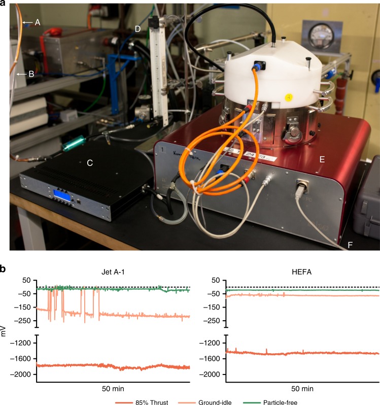
Fig. 2.
Aerosol exposure setup and particle deposition. a NACIVT deposition chamber setup for jet turbine aerosol exposure. A = Exhaust line; B = CO2 line; C = low-flow thermodenuder; D = rotameter for regulation of CO2 flow into the chamber (5%); E = NACIVT chamber; and F = USB connection to computer for online data collection. b Successful deposition of particles on cell cultures. Electrometer data collected within the deposition chamber show distinct precipitation voltage patterns for varying engine thrust levels and fuel types

