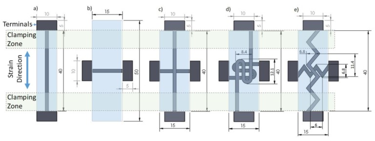
Figure 2.
CAD drawings for: (a) linear axial; (b) linear transverse; (c) linear biaxial; (d) switchback biaxial; and (e) sawtooth biaxial. All dimensions are in mm. Within each design, the black and light blue regions are TPU/MWCNT and pure TPU, respectively. The electrical connection terminals, clamping zone, and strain direction are also identified. The sample thickness in (a,b) is 1.0 mm and in (c–e) is 1.2 mm. The clamping zone size is 7.5 mm on each side, leaving a free length of 25 mm between the clamps.

