Figure 5.
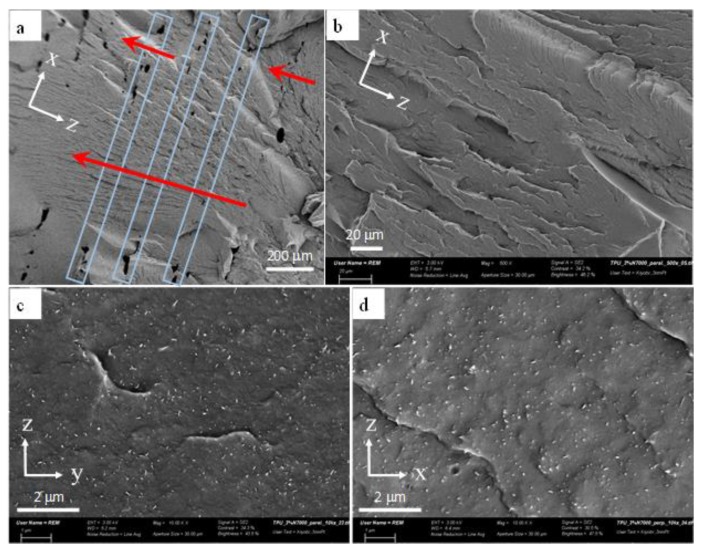
SEM micrographs of FFF 3D printed TPU/3 wt % MWCNT samples. x is the layer deposition direction (i.e., the direction of nozzle movement), y is the width direction and z is the height direction where layer stacking takes place. (a) x-z view of the interlayer bonds. The blue rectangles indicate the interlayer areas and the red arrows point the regions where the failure flows across the interlayer regions. (b) A view of x-z plane showing an intralayer region with no signs of large agglomerates. (c,d) The MWCNT dispersion and orientation in the planes normal (z-y) and parallel (x-z) to the layer deposition direction (x axis), respectively.

