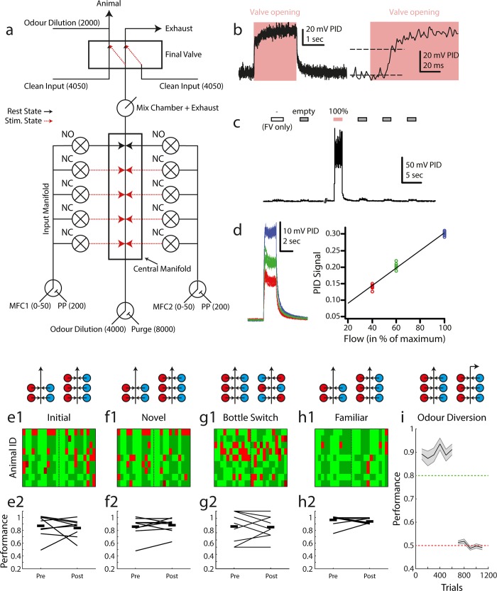
Fig 3. Odour delivery.
(a) Olfactometer schematic. Numerical values shown indicate supplied air flow in cubic centimeters per minute. Black / red lines indicate resting state (between trials) and odour delivery state air pathways respectively. (b) Example PID recorded odour trace. Left: entire recorded pulse, right: at higher temporal resolution. (c) Example recording from the olfactometer switching between final valve only (FV only), empty (non-odourised) input and odourised input (100%, red). (d) Output odour concentration is reliably controlled by airflow dilution. Left: 10 overlaid odour pulses during maximum MFC input (blue), 60% MFC input (green) and 40% MFC input (red). Right: summary of PID recorded odour signal in the three conditions. (e1) Map of trial performance before and after introduction of an extra valve set (as schematised above: red = odour 1, blue = odour 2) into the odour stimulus production, during the first odour pair discrimination learnt by this set of animals (n = 9). Each row corresponds to an animal, with each column in the row corresponding to a trial (pre-switch n = 12, post-switch n = 12). The vertical dashed line indicates the point at which new valves were introduced. Light green: hit, dark green: correct rejection, light red: false alarm, dark red: miss. (e2) Summary of data shown in (e1) showing mean performance before and after for each animal in the group (connecting black line, start and end values jittered for ease of visualisation). Thick black lines indicate the mean of the group pre- and post- new valve introduction. (f1), (f2), (g1), (g2), (h1), (h2) Same analysis as in (e1), (e2) but for novel and familiar odour pair discrimination respectively. (g1), (g2) shows performance on the novel odour pair task before and after a full bottle switch with randomised placement. (i) Performance in a standard odour pair discrimination (EB vs. AA) followed by diversion of the odour stream in the olfactometer final valve (mean +/- sem). Performance analyses in 100 trial bins for each animal.

