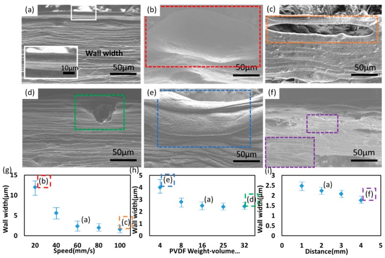
Figure 2.
(a) The morphology of 3D electrospun PVDF fibers with the spinneret size of 27 G, applied voltage at 1.6 kV, 16 wt % PVDF solution, 60 mm/s x-y stage speed and 2 mm spinneret-to-collector distance under SEM. The above processing conditions are selected as the basis. The inset shows a magnified view. SEM images showing the morphology of 3D electrospun PVDF fibers with respect to (b) 20 mm/s x-y stage speed (c) 100 mm/s x-y stage speed (d) 32 wt % PVDF solution (e) 8 wt % PVDF solution (f) 4 mm spinneret-to-collector distance. Plots showing the dependence of wall width with respect to (g) PVDF weight-volume percentage, (h) motion speed of the x-y stage, (f) spinneret-to-collector distance. The experimental data are the collection of ten samples, with the average values and error bars showing the distribution. The insets of red/orange/green/blue/purple dotted rectangle in (g–i) correspond to the NFES processing parameters in (b–f).

