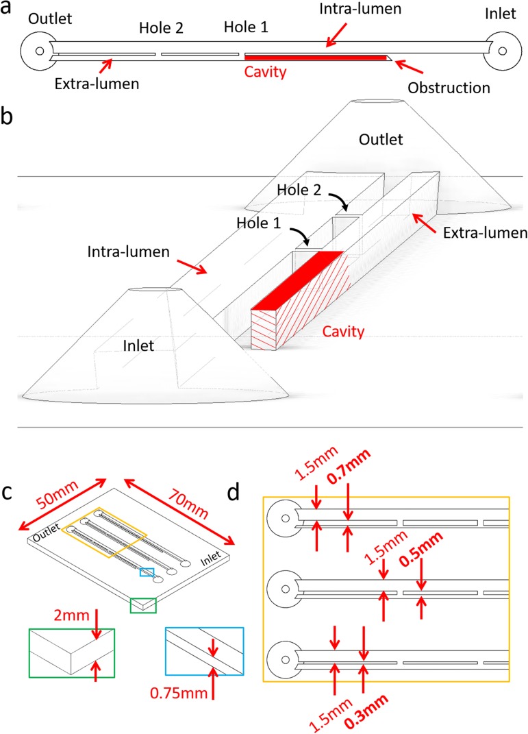
FIG. 2.
Top view (a) and 3D isometric view (b) of the model, illustrating a typical architecture and its relevant hydrodynamic regions (i.e., Inlet, Outlet, Hole 1, Hole 2, Cavity, and Intra/Extra-lumen). (c) Isometric view of the full SoC device. The blue and green boxes provide a zoomed-in view of the channel height and the SoC base, respectively. The yellow box provides a zoomed-in view of the proximal region of the SoC model. This is illustrated in (d) and comprises models with different septum thickness (in bold) of 0.3 mm, 0.5 mm, and 0.7 mm, and a constant intra-luminal width of 1.5 mm. Channels in this model have a rectangular cross section.

