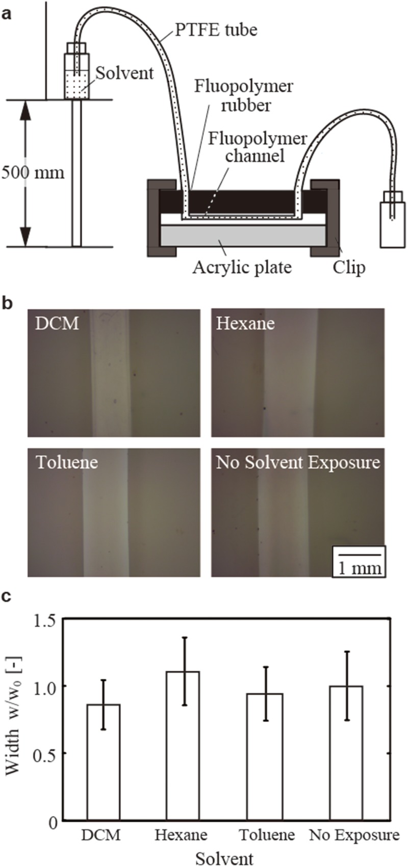
FIG. 5.
Continuous exposure of organic solvents to the PTFE channels. (a) Schematic illustration of the arrangement of the device. The solvents were delivered by elevating the container of the fluid above the ground level. (b) Optical micrographs showing the width of the channels. The films were delaminated to visualize the channels and measure their widths. (c) A graph showing the widths of the channel after the exposure to the solvents (characterized as their non-dimensional widths).

