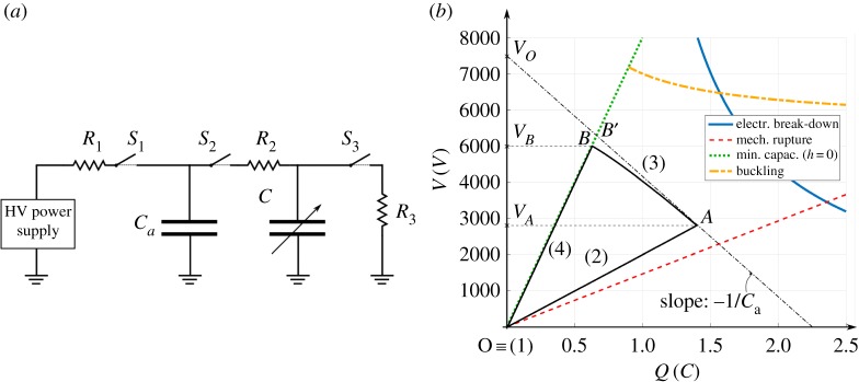
Figure 5.
(a) Conditioning circuit for the DEG PTO. (b) Charge-voltage, Q − V , plane representing the CD-DEG operating constraints (namely, electrical break-down, mechanical rupture, minimum capacitance configuration, electro-mechanical buckling) and example of conversion cycle (loop OABO). (Online version in colour.)

