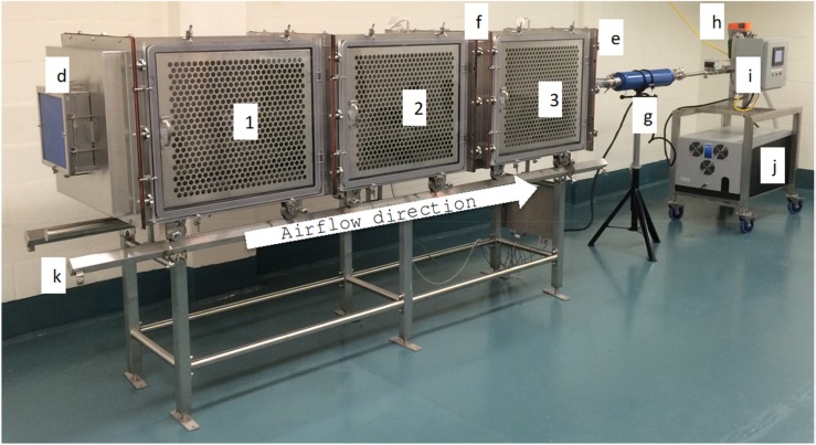
Figure 1.
System overview. (1) Cage number one, (2) cage number two, (3) cage number three, (d) high-efficiency particulate air (HEPA) filter inlet air, (e) HEPA filter exhaust air (not visible in the picture), (f) particle separator, (g) muffler, (h) airflow adjustment valve, (i) control panel, (j) pump installed in an insulated box, (k) support table with rails.

