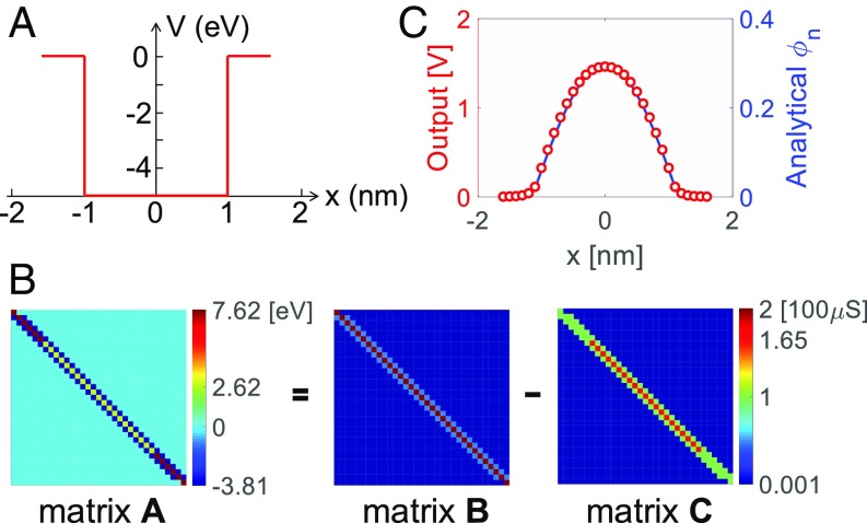
Fig. 4.
Solution of the Schrödinger equation in a cross-point circuit. (A) Rectangular well of potential V(x) adopted in the Schrödinger equation. The potential well has a depth of −5 eV and a width of 2 nm, while the solution is conducted on an overall width of 3.2 nm, discretized in 32 equal intervals. (B) Matrix A with size 33 × 33 obtained from the space discretization of the Schrödinger equation, and the two positive matrices B and C implemented in the cross-point arrays, with A = B − C. A conversion unit of 100 μS for 7.6195 eV was adopted in matrices B and C. The two conductance matrices share the same color bar. The ground-state eigenvalue is −4.929 eV, which was mapped into the conductance (65 μS) of the TIA feedback resistors. (C) Discrete ground-state eigenfunction obtained as the simulated output voltage in the cross-point circuit compared with the analytical solutions. Note that the peak voltage is around the supply voltage 1.5 V of the OA due to saturation.

