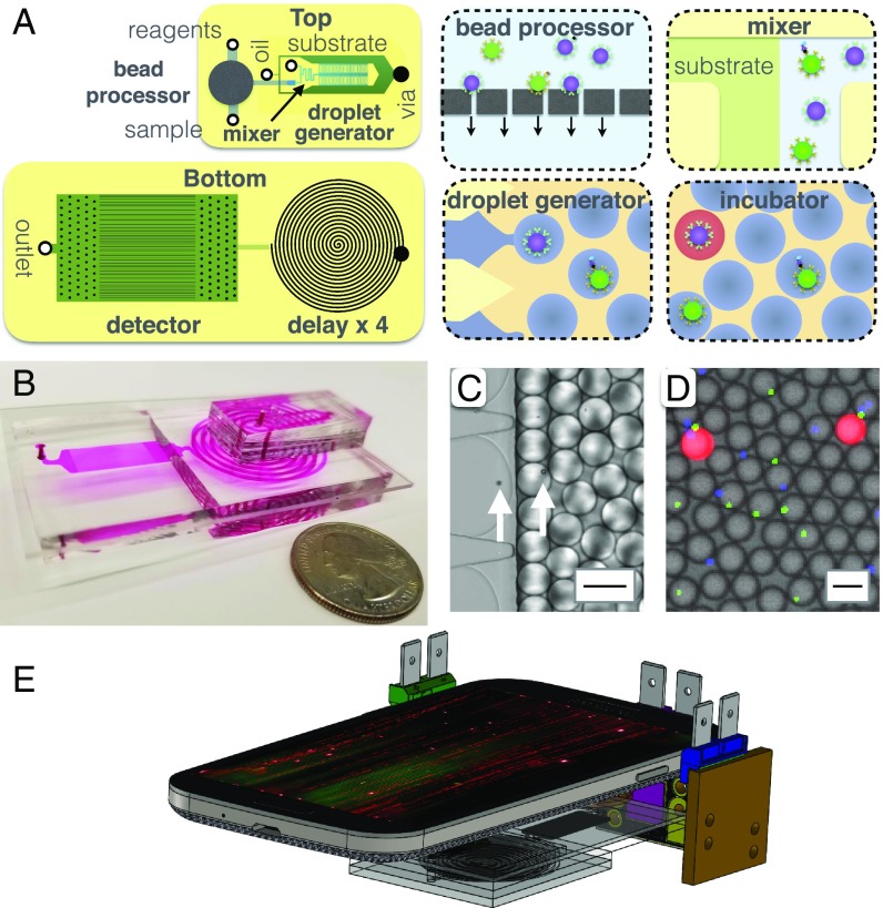
Fig. 2.
Integrated MD workflow. (A) A schematic of the MD chip, showing both a top view and a bottom view. Each cartoon shows a schematic of the modules that are incorporated onto the MD. (B) A photograph of the disposable MD chip, with the channels filled with dye to make them visible. (C) A micrograph showing the droplet generator encapsulate microbeads into d = 40 m droplets. The arrows highlight the microbeads. (Scale bar = 50 m.) (D) A fluorescence micrograph of the droplets after the delay line. (Scale bar = 50 m.) (E) A schematic of the MD platform, consisting of a mobile phone, three light sources, and the disposable MD chip.

