Abstract
Adaptive optics systems have been integrated in many imaging modalities in order to correct for aberrations that are introduced by samples and optical elements. Usually, the optical system has access to a guide star (i.e., a point-like structure that is smaller than the diffraction limit). This guide star can be used as a beacon for adaptive optics enhancement. In contrast, for spectroscopy and densely-labeled fluorescent samples, the signal is diffused throughout the entire beam path and is not confined to a well-defined point-like structure. Here, we show analytically and experimentally that, in these scenarios, adaptive optics systems are expected to yield significantly lower signal enhancement than when a guide star is available. We discuss adaptive optics’ performance degradation for different imaging modalities (e.g., confocal, multi-photon microscopy) and identify solutions to overcome low signal enhancements.
1. Introduction
Optical imaging modalities often suffer from degraded performances due to aberrations and refractive index mismatches within the optical path. This long-standing issue was first addressed by astronomers who developed and implemented Adaptive Optics (AO) systems in ground-based telescopes to measure and correct atmospheric aberrations and enable diffraction limited images of distant stars [1]. Following the success achieved by AO in astronomy, the same concept was applied to ocular imaging to enable aberration-free imaging of retinal photoreceptors [2–4]. In the past two decades AO techniques have been extensively applied to a variety of optical microscopy modalities such as wide field [5,6], confocal [7], multiphoton [8–10] and super-resolution [11–13].
Adaptive optics systems have improved the capabilities of optical microscopes to approach their optimal performances by improving image contrast and resolution as well as enhancing the signal-to-noise ratio (SNR). However, the extent to which AO can improve image quality is highly variable in the literature. Reported signal enhancements range from few percent to more than ten-fold [12,14–17]. The different performances can only partially be attributed to system parameters (e.g. finite spatial and temporal resolutions, photon noise, isoplanatism), especially because modern tools, such as phase modulators operating at a kHz rate with thousands of degrees of freedom and low noise cameras, can effectively address system-related aberrations. In this context, in fluorescence microscopy applications, the labeling density or the size of the “guide star” have been observed to strongly affect AO performances [18], but the mechanism of such dependence has not been described thus hindering the ability to implement effective improvements to AO protocols.
Here we analyze the dependence of AO performances on labeling density both theoretically and experimentally in the context of confocal microscopy and demonstrate how it dramatically affects the ability of AO systems to enhance signal intensity. In practical scenarios, the degradation of AO performances is particularly relevant in microscopy when fluorescent labeling is diffused within the sample (i.e. fluorescent sea) and it is difficult to ensure the existence of a single fluorescence bead within the illumination path, or in spectroscopy measurements where the signal can arise from any location within the illumination path. We show that, in the context of confocal microscopy and spectroscopy of diffused signals, epi-detection configurations do not properly estimate optical aberrations in the system and have little sensitivity to proper image quality metrics; as a result, AO protocols are destined to suboptimal results in these scenarios. To quantify this effect, we analytically model the degradation of AO signal enhancement in a ‘fluorescent sea’ scenario compared to a point-like guide star and experimentally verify the prediction described by our model. Using aberrating layers we characterize the challenge presented by diffused signals when AO procedures are applied. We further compare the situation of confocal microscopy with multi-photon microscopy and describe potential solutions for future improvements.
2. Experimental configuration
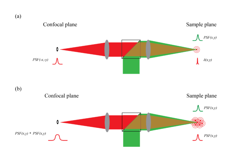
Image formation in fluorescent confocal microscopy is based on imaging a focal point within the sample onto a confocal plane where a pinhole is placed to reject out-of-focus light. Scanning such focal point within the sample and mapping the intensity measured behind the pinhole yields the image. The pinhole can be a mask, typically a circular aperture of fixed diameter; alternatively, a CCD camera can be placed in the confocal plane and the intensity from only pre-selected pixels is detected [19,20]. The most common configuration for confocal microscopy is in epi-detection where illumination and collection light utilize the same objective lens. Under these circumstances, the focal point generated through a sample is imaged back onto the confocal plane of the pinhole through the same light-path. In this situation, if the sample can be regarded as a ‘fluorescent sea’, when performing a confocal scanning, the intensity distribution at each point in the confocal plane does not reveal the intensity distribution of the corresponding point scanned within the sample but its autocorrelation [21]. This interesting phenomenon can be intuitively understood: when an infinitely small fluorescent bead is excited within the sample, the intensity revealed in the confocal plane is the convolution of the point spread function of the detection path with a delta function [Fig. 1(a)]; for identical illumination and detection paths, this yields the inverse of the illumination PSF. In contrast, when every point in the sample generates fluorescence [Fig. 1(b)], we do not have access to the intensity distribution of “a single point” of the sample; instead, in the confocal plane, the intensity distribution of “a single point” in the sample is the convolution of the detection path with the “single point” as created by the illumination path (i.e. the illumination PSF). Because the illumination path and detection path are identical but inverted optical systems, the final image on the confocal plane is a convolution of the intensity distribution on the sample with an inverse version of itself, which is the autocorrelation. This property has important consequences for signal enhancement within AO systems as we will see next.
Fig. 1.
Schematics of a confocal configuration focused on a fluorescent bead (a) or on a fluorescent sea (b). The sample plane is back imaged onto the confocal plane generating either an inverse PSF (a) or the autocorrelation of the PSF (b).
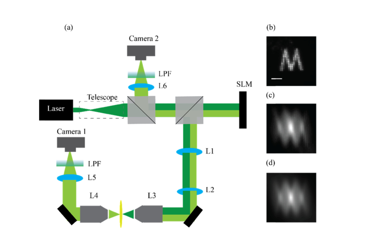
We demonstrated this important property experimentally with the setup in Fig. 2(a). We expanded a polarized Ar-Ion laser beam (Edmund optics, λ = 514nm) and reflected it off the surface of a spatial light modulator (SLM, Hamamatsu X10468). We imaged the plane of the SLM using a 4-f imaging system (L1, L2, f = 150mm) onto the back aperture of an objective lens (L3, 4X 0.1NA) and focused it onto a fluorescent sample (Rhodamine B solution, Sigma). The fluorescent focal point generated at the sample was imaged using two arms: one in transmission and one in epi-detection. In the transmission arm we collected the light using an identical objective lens as the one used for focusing (L4, 4X 0.1NA), and imaged the focal point onto a camera (camera 1) using a second lens (L5, f = 200mm) in an infinite conjugate imaging system. In the epi-detection arm we used the back-emitted light to image the focal point; in this arm, the collected light is reflected again off the SLM surface before being focused onto the camera (camera 2), hence, any aberration presented by the SLM will be sampled twice throughout the back-and-forth paths of light. In both arms we placed an emission filter to block the excitation laser from hitting the camera. The transmission arm of the setup in Fig. 2 can measure the true intensity distribution at the sample, as it directly captures the pattern before it is reimaged onto the confocal plane. The epi-detection arm of the setup in Fig. 2 features camera 2 where one would place a confocal pinhole to reject out-of-focus light and thus allows us to study a confocal microscopy configuration and a ‘fluorescent sea’ as a sample.
Fig. 2.
(a) Setup: The excitation beam (dark green) is reflected off the SLM surface and focused onto a ‘fluorescent sea’ sample. The emission light (bright green) is collected both is transmission (camera 1) and in reflection/epi-detection (camera 2). Only the reflected light is back imaged onto the SLM surface before being captured by the camera. (b) An artificial aberration of the letter ‘M’ generated by the SLM and captured in transmission by camera 1 (scale bar = 60 µm). (c) The intensity distribution as captured in epi-detection by camera 2. (d) The computed autocorrelation of the letter ‘M’ presented in (b).
To demonstrate the key feature of this configuration, i.e. the detection of the autocorrelation of the sample intensity distribution on the confocal plane, we used the SLM to shape the phase of the illumination light and generate a letter ‘M’ in the sample plane. We then recorded the intensity distribution in both cameras: in transmission (camera 1) we observed the well expected letter ‘M’ [Fig. 2(b)]; in the epi-detection arm (camera 2), as expected, we observed the autocorrelation of the ‘M’ pattern [Fig. 2(c)] as it is clear by comparing it with the computed autocorrelation image [Fig. 2(d)].
We note that although the aberration in our setup was introduced at the back aperture of the objective lens (by conjugating it to the SLM plane), it is equivalent to a scenario where a single layered aberration is introduced between the objective lens and the focal plane. In both cases the intensity distribution at the focal plane will correspond to the power spectrum of the aberration phase map [22].
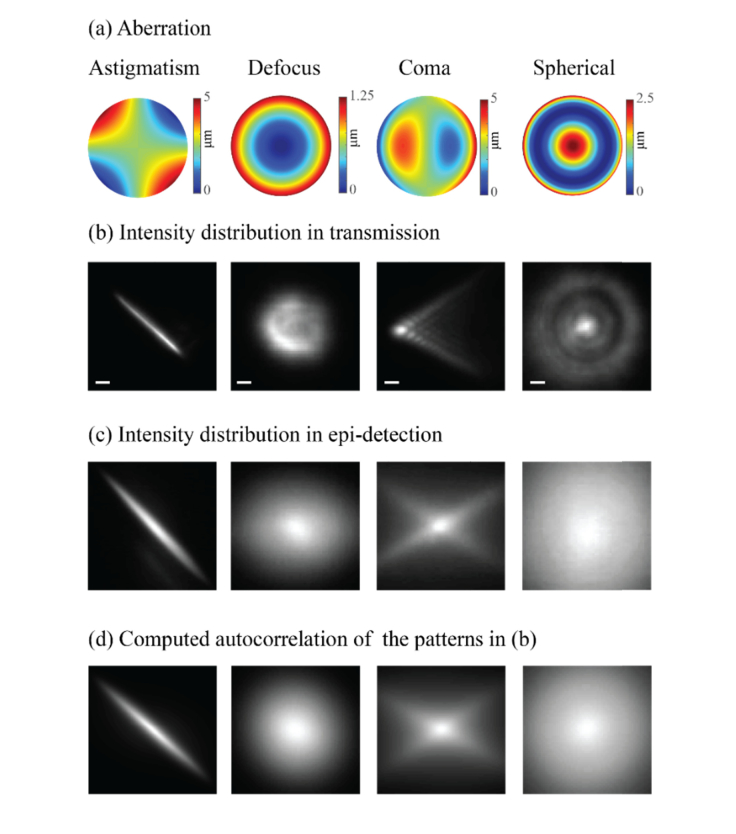
In the same way the intensity distribution on the sample focal plane is not faithfully reproduced in the confocal plane of epi-detection microscopes, any aberration introduced by the sample or optical system will not be probed properly when viewed through the epi-detection path; indeed, it will be detected as an autocorrelation of its intensity distribution. To demonstrate this concept, we used the setup in Fig. 2, focused light into a single point on the fluorescent sample and introduced four primary aberrations (astigmatism, defocus, coma and spherical) through the SLM. Figure 3 shows the results of the aberrated intensity distributions as recorded by the transmission and epi-detection arms. Figure 3(a) shows the aberrations introduced by the SLM, Fig. 3(b) shows the resulting intensity distribution recorded through the transmission arm (camera 1), Fig. 3(c) shows the intensity distribution recorded using the epi-detection arm (camera 2). For comparison, the autocorrelations of the patterns of Fig. 3(b) were numerically computed and are presented in Fig. 3(d).
Fig. 3.
(a) Four primary aberrations projected by the SLM. (b) The intensity distribution captured in transmission by camera 1 (scale bar = 10 µm). (c) The epi-detection intensity distribution recorded by camera 2. (d) The computed autocorrelation functions of the intensity distribution presented in (b).
Figure 3 emphasizes the marked difference between the true illumination pattern generated within the sample (i.e. the transmitted pattern) and the pattern as measured in epi-detection. If a pinhole were to be placed in the confocal plane (i.e. the location of camera 2), the detected light would not be a proper representation of the actual illumination pattern generated within the sample. Instead, the pinhole will sample the intensity at one location of the autocorrelation function, which is poorly sensitive to local intensity changes and therefore less affected by the AO procedure as we will later show and quantify.
3. Results
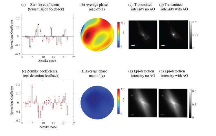
We set out to demonstrate how the epi-detection path on the confocal plane is not sensitive to the intensity variations in the sample plane and thus results in suboptimal AO enhancement. First, we show that using the epi-detection arm as feedback for AO procedure leads to faulty estimation of the aberration and decreases AO enhancement. To do so, within the setup, we introduced an aberration by spreading transparent glue on a microscope slide and inserting it between the objective lens (L3) and the fluorescent substrate thus causing a deformation of the focal point. We applied an iterative algorithm to correct for the induced aberration. The algorithm was designed to enhance a single point on the image by measuring the intensity response to the projection of each Zernike polynomial and its’ inverse from which the coefficient value was estimated [7,16]. We performed the AO correction twice, once using the maximal intensity of the image in the transmission path as a feedback (i.e. true feedback) and a second time using the maximal intensity as measured in the epi-detection path as a feedback (i.e. the autocorrelation feedback). The transmission image feedback procedure can be considered equivalent to a procedure using a small point-like guide star, as it is a direct measure of the intensity distribution on the sample. The transmission image feedback yielded highly repeatable results for ten different trials: the coefficients of the calculated Zernike modes showed small variations [Fig. 4(a)], the average of all phase maps had a clear structure [Fig. 4(b)] and the procedure resulted in ~2-fold enhancement of the focal intensity [Figs. 4(c) and (d)]. Instead, using the epi-detection feedback, each repetition of the algorithm yielded a different set of Zernike coefficients, with large variations [Fig. 4(e)]. The average phase map obtained using the epi-detection arm appeared flat as the different iterative processes yielded uncorrelated phase maps [Fig. 4(f)] and a negligible increase in intensity was obtained [Figs. 4(g) and (h)].
Fig. 4.
(a) The Zernike coefficients obtained by the algorithm using the transmission arm (camera 1) as feedback. (b) The average phase map of the coefficients from (a). (c) The initial intensity distribution recorded by camera 1 through the glue aberration (scale bar = 15 µm). (d) The final intensity distribution recorded by camera 1 after projecting the phase map shown in (b). (e) The Zernike coefficients obtained by the algorithm using the epi-detection arm (camera 2) as feedback. (f) The average phase map of the coefficients from (e). (g) The initial intensity distribution recorded by camera 2 through the glue aberration (scale bar = 15 µm). (h) The final intensity distribution recorded by camera 2 after projecting the phase map shown in (f).
Considering the results presented in Fig. 4 one might come to an immediate conclusion that as long as a guide-star is used throughout the optimization process, the spectroscopic/diffused-fluorescence measurement can efficiently benefit from the AO correction. However, in the next section we caution against such a general conclusion and we show that even when a significant enhancement is obtained at the sample plane (for example using true transmitted intensity as feedback or using a truly point-like guide star), such enhancement is not necessarily captured by the epi-detection arm.
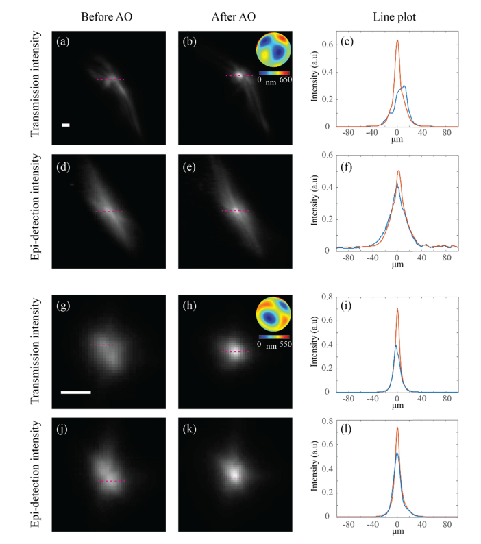
To do so, we introduced again an aberration by spreading transparent glue on a microscope slide and inserting it between the objective lens (L3) and the fluorescent substrate to obtain a deformed focal point [Fig. 5(a)]. Then we applied the same iterative algorithm as before to correct for the induced aberration using the maximal intensity of the image in the transmission path as feedback. The procedure resulted in ~2-fold enhancement of the focal intensity and of the total energy was contained within the FWHM of the focal point [Figs. 5(b) and 5(c)]. We then recorded the intensity distribution of the epi-detection arm before and after the enhancement process [Figs. 5(d) and 5(e) respectively]. On the epi-detection arm only enhancement was observed [Fig. 5(f)], i.e. a “point-like guide-star” enhancement at the sample plane would have yielded 5-fold greater enhancement than the one indicated by the epi-detection image at the confocal plane. Yet, if the AO correction procedure produces a nearly perfect correction, the enhancement at the confocal plane will approach the true enhancement at the sample plane. To show such behavior we repeated the experiment with a milder glue aberration to enable a better AO correction. As before, the optimization process was performed using the transmission arm as feedback, which in this case yielded a sharp focal point as seen from Figs. 5(g) and 5(h). Due to the tight confinement of the focal point which contained of the total energy within the FWHM, also on the epi-detection arm a similar result (with a slight broadening as expected from the autocorrelation properties [23]) was obtained [Figs. 5(j) and 5(k)]. Comparing the line plots of the transmission arm [Fig. 5(i)] and the epi-detection arm [Fig. 5(l)] it is evident that for this aberration the signal enhancement observed by the two arms is not significantly different. The reason why AO correction performed using the true enhancement (or, equivalently, a guide-star) will sometimes translate into a negligible enhancement at the epi-detection arm while in other scenarios yield a significant improvement will be discussed and quantified in the following section.
Fig. 5.
(a, g) Intensity distributions recorded in transmission (camera 1) through two different glue aberrations (scale bar = 12 µm). (b, h) The intensity distributions in transmission after performing the AO optimization using the transmission arm as a feedback. The insets show the final phase map projected by the SLM. (c, i) Line plots comparing the peaks of the intensity distributions without (blue) and with (red) AO correction. (d, j) Intensity distributions recorded in epi-detection (camera 2) through the glue aberrations. (e, k) Intensity distributions in epi-detection after performing the same AO optimization as in (b) and (h) respectively, i.e. the same phase maps as shown in the insets of (b, h) were applied here. (f, l) Line plots comparing the peaks of the intensity distributions without (blue) and with (red) AO correction.
4. Analytical model
To understand the phenomenon in depth, we built a model using the experimental scenario of Fig. 5, i.e. we compared the true intensity enhancement achieved on the sample plane (obtained either using the transmission arm feedback or using a point guide star) with the one observed by the epi-detection arm.
The aberration introduced by the sample enlarges the diffraction limited spot and spreads its intensity onto a larger area; here, we denote this area to be N times larger than the diffracted limited spot and for simplicity we treat it as discrete, i.e. the intensity is equally spread onto N diffraction limited points of intensity . Suppose one is able to achieve an enhancement of the central point through an AO procedure by a factor of ‘k’, i.e. the intensity at that given point is: . As the total energy does not change, all other points will have a reduced intensity of:
| (1) |
However, as previously demonstrated, the epi-detection microscope is not sampling the actual intensity at the sample plane, but its autocorrelation. Let’s then compare the autocorrelation intensity before and after enhancement. Before the AO procedure, the central autocorrelation point had intensity:
| (2) |
After the AO procedure, from Eq. (1) we can derive the intensity of the central autocorrelation point to be:
| (3) |
As a result, the enhancement following the AO procedure is obtained by dividing Eqs. (3) and (2):
| (4) |
In the ideal scenario where the AO procedure can refocus all energy back into a single point, i.e. , the autocorrelation is enhanced by k times, exactly reporting the same enhancement of the sample plane. For the enhancement in epi-detection (i.e. Equation (4)) reduces to 1 meaning that the AO enhancement is negligible in the autocorrelation plane. Equation (4) can be applied to the reported results of Fig. 5; the focal point shown in Fig. 5(b) is estimated to be ~100 pixels at FWHM, while the aberration prior to the enhancement [Fig. 5(a)] is estimated to be ~10 times larger. Hence, by substituting into Eq. (4), the enhancement is 21% in agreement with our experimental results.
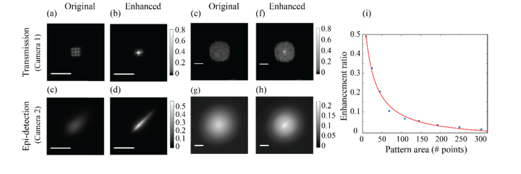
The prediction given by our model is that for a given AO procedure (i.e. same k), larger aberrations/illumination (i.e. larger values of N) will yield smaller signal enhancement in the epi-detection arm significantly deviating from the true enhancement that one would obtain at the sample plane if accurate feedback were to be used. To verify this prediction, we generated an illumination pattern containing 9 discrete points [Fig. 6(a)] and, using the SLM, we enhanced the central point by a factor of ~6.5 [Fig. 6(b)]. On the epi-detection arm we observed a ~3-fold enhancement [Figs. 6(c) and 6(d)], i.e. approximately half of the enhancement value at the sample. Next, we generated a much wider pattern containing 193 points [Fig. 6(e)] and enhanced the central point by a similar factor of ~6.5 [Fig. 6(f)]. As we expected, on the epi-detection arm in this scenario we observed only ~1.16-fold enhancement [Figs. 6(g) and 6(h)]. To quantitatively verify the predictions of our model, we then used a series of such patterns with different areas and for each pattern we enhanced a single point and compared the enhancement obtained in the transmission path (camera 1) with that obtained in the epi-detection path (camera 2). Consistent with our model, for wide intensity distributions the enhancement measured on the epi-detection path was much lower than the actual enhancement measured in the transmission path (i.e. in the sample plane). However, as the intensity distribution area decreased, the enhancement in the epi-detection arm approached the actual enhancement value in the sample plane, [Fig. 6i, blue dots]. We fitted the experimental data to our model; the ratio between the actual and observed enhancements can be obtained by dividing Eq. (4) by k. Leaving k as a free parameter we found the data to be in good agreement with the model [Fig. 6(i), red line] and the value of k was calculated by the fitting process to be 6.51.
Fig. 6.
(a) An artificial aberration composed out of 9 identical points (scale bar = 60 µm). (b) The central point in (a) was enhanced by ~6.5-fold. (c, d) The intensity distribution of (a) and (b) respectively as seen in epi-detection. (e) An artificial aberration composed out of 193 identical points (scale bar = 60 µm). (f) The central point in (e) was enhanced by ~6.5-fold. (g, h) The intensity distribution of (e) and (f) respectively as seen in epi-detection. (i) The enhancement ratio between the true enhancement on the sample (recorded in transmission) and the enhancement observed in epi-detection for varying sizes of aberrations (blue dots). The data agrees with the prediction of our model as seen by the red plot.
5. Discussion
In ophthalmology applications, it has been known that when a double-pass configuration is used to measure the aberrations of the eye from retina reflections using a wave front sensor, the measurement will yield a false phase map [21]. This failure of the wave-front measurement is caused by the light passing twice through the same aberrating medium which causes the phase variations of even aberrations to double while odd aberrations cancel out. A similar phenomenon is described here, in the realm of confocal fluorescence microscopy or spectroscopy. For biomedical applications, the double pass configuration offered by epi-detection is an important feature that enables access to the sample from just one side, while providing high 3D resolution. In such configuration, if a signal can arise from any locations within the sample without point-like guide stars, direct measurement of the phase map is prone to failure. In fluorescent microscopy, to avoid measuring the phase map directly, image-based AO approaches have been applied where the phase aberration is estimated by enhancing some image parameter such as the maximal intensity [24,25]. Such indirect approaches have been shown to be successful in scenarios where direct wave-front measurements fail (e.g. within scattering materials [25]) because they are not bounded by the limited ability of a wave-front sensor to accurately measure the phase aberrations. Here we showed that also image-based AO approaches fail in this experimental scenario: in a ‘fluorescent-sea’ scenario, the intensity response through the double pass (i.e. epi-detection) path is much lower than the true enhancement that could be obtained at the sample. This lack of sensitivity to intensity variations will yield poor results when the confocal intensity is used as an indicator for an iterative phase correction. Accordingly, denser labeled fluorescent samples and spectroscopic measurements are expected to yield lower improvements of image quality when AO procedures are applied.
In the context of two photon microscopy, Ji et al [18] have reported a similar trend where increase in the size of guide star leads to a decrease of signal enhancement via AO. This observation is probably dominated by a different phenomenon as the illumination and detection paths are distinct in multiphoton setups. In two photon microscopy a thick and densely labeled sample should provide the same amount of light emission regardless of the focal quality; in fact, while tightly focused beams provide high photon flux within the illuminated voxel, increasing the illumination area compensates the intensity loss at the focus by increasing the volume from which the signal can originate [26]. Hence, with highly dense samples, a poor AO enhancement is expected because focal confinement does not affect the signal intensity. The signal from higher order non-linearity processes such as three photon emission is better suited for densely labeled samples [27].
To overcome the problem arising from the identical illumination and detection light paths in a double-pass configuration, Artal et al. had suggested to make the illumination path smaller and under-fill the objective lens [28]. In this configuration, light is aberrated by the sample only once, which enables the correct phase map measurement. However, in context of confocal microscopy, this solution may not be viable because the confocal modality relies on the tight focusing of the illuminating beam. Different approaches can potentially provide a better framework for enhancement in this case. For example, coherence gating allows to collect light from a confined region within the sample, which can mimic the existence of a guide star and avoid the ‘fluorescent sea’ scenario [29]. Similarly, a wave front sensor can be placed after the confocal pinhole, which rejects light from surrounding regions [30]. These solutions were shown to enable a better estimation of the aberrations measured from a reflecting surface and can be also applied in the context of fluorescent sea, yet they are difficult to implement and require delicate alignment and careful choice of specifications such as broadened emission or confocal pinhole adjustment. Computational approaches to handle the complexity provided by the autocorrelation outcome in the image plane such as phase-retrieval algorithms [31] or minimizing the area of the autocorrelation intensity distribution as recently suggested by Stern et al. [32] can also provide a way to enable correct estimations of the phase aberrations. Yet, the convergence of such algorithms still imposes a severe limitation on the complexity of the aberrations which can be handled.
A viable approach to overcome the problem we have described here is to work in a dual-axis configuration so that the detection arm samples light only from a small region within the illuminated sample [33]. The concept of a dual-axis configuration is that the illumination and detection paths cross each other only within a small region, hence, only light emitted from that region will contribute to the enhancement process. The small overlapping region of the detection and illumination paths can be understood as a “geometrical bead”, i.e. in the absence of a physical bead which can serve as a well confined emitting guide-star, the overlapping region effectively confines the relevant emission to a small volume in a geometrical manner. Such a configuration was shown to enable significant AO enhancement in confocal Brillouin spectroscopy, which represents an extreme ‘fluorescent sea’ scenario [16].
Acknowledgement
The authors thank Susana Marcos for fruitful discussions.
Funding
National Institutes of Health (K25EB015885, R33CA204582, and U01CA202177); National Science Foundation (CMMI-1537027); Glaucoma Research Foundation (Shaffer’s Grant).
References
- 1.Beckers J. M., “Adaptive Optics for Astronomy – Principles, Performance, and Applications,” Annu. Rev. Astron. Astrophys. 31(1), 13–62 (1993). 10.1146/annurev.aa.31.090193.000305 [DOI] [Google Scholar]
- 2.Roorda A., Williams D. R., “The arrangement of the three cone classes in the living human eye,” Nature 397(6719), 520–522 (1999). 10.1038/17383 [DOI] [PubMed] [Google Scholar]
- 3.Roorda A., Romero-Borja F., Donnelly Iii W., Queener H., Hebert T., Campbell M., “Adaptive optics scanning laser ophthalmoscopy,” Opt. Express 10(9), 405–412 (2002). 10.1364/OE.10.000405 [DOI] [PubMed] [Google Scholar]
- 4.Marcos S., Werner J. S., Burns S. A., Merigan W. H., Artal P., Atchison D. A., Hampson K. M., Legras R., Lundstrom L., Yoon G., Carroll J., Choi S. S., Doble N., Dubis A. M., Dubra A., Elsner A., Jonnal R., Miller D. T., Paques M., Smithson H. E., Young L. K., Zhang Y., Campbell M., Hunter J., Metha A., Palczewska G., Schallek J., Sincich L. C., “Vision science and adaptive optics, the state of the field,” Vision Res. 132, 3–33 (2017). 10.1016/j.visres.2017.01.006 [DOI] [PMC free article] [PubMed] [Google Scholar]
- 5.Azucena O., Crest J., Kotadia S., Sullivan W., Tao X., Reinig M., Gavel D., Olivier S., Kubby J., “Adaptive optics wide-field microscopy using direct wavefront sensing,” Opt. Lett. 36(6), 825–827 (2011). 10.1364/OL.36.000825 [DOI] [PubMed] [Google Scholar]
- 6.Li J., Beaulieu D. R., Paudel H., Barankov R., Bifano T. G., Mertz J., “Conjugate adaptive optics in widefield microscopy with an extended-source wavefront sensor,” Optica 2(8), 682–688 (2015). 10.1364/OPTICA.2.000682 [DOI] [Google Scholar]
- 7.Booth M. J., Neil M. A. A., Juskaitis R., Wilson T., “Adaptive aberration correction in a confocal microscope,” Proc. Natl. Acad. Sci. U.S.A. 99(9), 5788–5792 (2002). 10.1073/pnas.082544799 [DOI] [PMC free article] [PubMed] [Google Scholar]
- 8.Débarre D., Botcherby E. J., Watanabe T., Srinivas S., Booth M. J., Wilson T., “Image-based adaptive optics for two-photon microscopy,” Opt. Lett. 34(16), 2495–2497 (2009). 10.1364/OL.34.002495 [DOI] [PMC free article] [PubMed] [Google Scholar]
- 9.Wang K., Sun W., Richie C. T., Harvey B. K., Betzig E., Ji N., “Direct wavefront sensing for high-resolution in vivo imaging in scattering tissue,” Nat. Commun. 6(1), 7276 (2015). 10.1038/ncomms8276 [DOI] [PMC free article] [PubMed] [Google Scholar]
- 10.Wang K., Milkie D. E., Saxena A., Engerer P., Misgeld T., Bronner M. E., Mumm J., Betzig E., “Rapid adaptive optical recovery of optimal resolution over large volumes,” Nat. Methods 11(6), 625–628 (2014). [DOI] [PMC free article] [PubMed] [Google Scholar]
- 11.Booth M., Andrade D., Burke D., Patton B., Zurauskas M., “Aberrations and adaptive optics in super-resolution microscopy,” Microscopy (Oxf.) 64(4), 251–261 (2015). 10.1093/jmicro/dfv033 [DOI] [PMC free article] [PubMed] [Google Scholar]
- 12.Zheng W., Wu Y., Winter P., Fischer R., Nogare D. D., Hong A., McCormick C., Christensen R., Dempsey W. P., Arnold D. B., Zimmerberg J., Chitnis A., Sellers J., Waterman C., Shroff H., “Adaptive optics improves multiphoton super-resolution imaging,” Nat. Methods 14(9), 869–872 (2017). [DOI] [PMC free article] [PubMed] [Google Scholar]
- 13.Patton B. R., Burke D., Owald D., Gould T. J., Bewersdorf J., Booth M. J., “Three-dimensional STED microscopy of aberrating tissue using dual adaptive optics,” Opt. Express 24(8), 8862–8876 (2016). 10.1364/OE.24.008862 [DOI] [PubMed] [Google Scholar]
- 14.Ji N., Milkie D. E., Betzig E., “Adaptive optics via pupil segmentation for high-resolution imaging in biological tissues,” Nat. Methods 7(2), 141–147 (2010). 10.1038/nmeth.1411 [DOI] [PubMed] [Google Scholar]
- 15.Wright A. J., Poland S. P., Girkin J. M., Freudiger C. W., Evans C. L., Xie X. S., “Adaptive optics for enhanced signal in CARS microscopy,” Opt. Express 15(26), 18209–18219 (2007). 10.1364/OE.15.018209 [DOI] [PubMed] [Google Scholar]
- 16.Edrei E., Scarcelli G., “Brillouin micro-spectroscopy through aberrations via sensorless adaptive optics,” Appl. Phys. Lett. 112(16), 163701 (2018). 10.1063/1.5027838 [DOI] [PMC free article] [PubMed] [Google Scholar]
- 17.Thompson J. V., Throckmorton G. A., Hokr B. H., Yakovlev V. V., “Wavefront shaping enhanced Raman scattering in a turbid medium,” Opt. Lett. 41(8), 1769–1772 (2016). 10.1364/OL.41.001769 [DOI] [PubMed] [Google Scholar]
- 18.Ji N., Sato T. R., Betzig E., “Characterization and adaptive optical correction of aberrations during in vivo imaging in the mouse cortex,” Proc. Natl. Acad. Sci. U.S.A. 109(1), 22–27 (2012). 10.1073/pnas.1109202108 [DOI] [PMC free article] [PubMed] [Google Scholar]
- 19.Huff J., “The Airyscan detector from ZEISS: confocal imaging with improved signal-to-noise ratio and super-resolution,” Nat. Methods 12(12), i (2015). 10.1038/nmeth.f.388 [DOI] [Google Scholar]
- 20.York A. G., Parekh S. H., Dalle Nogare D., Fischer R. S., Temprine K., Mione M., Chitnis A. B., Combs C. A., Shroff H., “Resolution doubling in live, multicellular organisms via multifocal structured illumination microscopy,” Nat. Methods 9(7), 749–754 (2012). 10.1038/nmeth.2025 [DOI] [PMC free article] [PubMed] [Google Scholar]
- 21.Artal P., Marcos S., Navarro R., Williams D. R., “Odd aberrations and double-pass measurements of retinal image quality,” J. Opt. Soc. Am. A 12(2), 195–201 (1995). 10.1364/JOSAA.12.000195 [DOI] [PubMed] [Google Scholar]
- 22.Goodman J. W., Introduction to Fourier optics (Roberts and Company Publishers, 2005). [Google Scholar]
- 23.Edrei E., Nikolic M., Scarcelli G., “Improving localization precision of Brillouin measurements using spectral autocorrelation analysis,” J. Innov. Opt. Health Sci. 10(06), 1742004 (2017). 10.1142/S1793545817420044 [DOI] [Google Scholar]
- 24.Booth M. J., “Adaptive optical microscopy: the ongoing quest for a perfect image,” Light Sci. Appl. 3(4), 165 (2014). 10.1038/lsa.2014.46 [DOI] [Google Scholar]
- 25.Ji N., “Adaptive optical fluorescence microscopy,” Nat. Methods 14(4), 374–380 (2017). 10.1038/nmeth.4218 [DOI] [PubMed] [Google Scholar]
- 26.Katz O., Small E., Guan Y., Silberberg Y., “Noninvasive nonlinear focusing and imaging through strongly scattering turbid layers,” Optica 1(3), 170–174 (2014). 10.1364/OPTICA.1.000170 [DOI] [Google Scholar]
- 27.Horton N. G., Wang K., Kobat D., Clark C. G., Wise F. W., Schaffer C. B., Xu C., “In vivo three-photon microscopy of subcortical structures within an intact mouse brain,” Nat. Photonics 7(3), 205–209 (2013). 10.1038/nphoton.2012.336 [DOI] [PMC free article] [PubMed] [Google Scholar]
- 28.Artal P., Iglesias I., López-Gil N., Green D. G., “Double-pass measurements of the retinal-image quality with unequal entrance and exit pupil sizes and the reversibility of the eye’s optical system,” J. Opt. Soc. Am. A 12(10), 2358–2366 (1995). 10.1364/JOSAA.12.002358 [DOI] [PubMed] [Google Scholar]
- 29.Rueckel M., Mack-Bucher J. A., Denk W., “Adaptive wavefront correction in two-photon microscopy using coherence-gated wavefront sensing,” Proc. Natl. Acad. Sci. U.S.A. 103(46), 17137–17142 (2006). 10.1073/pnas.0604791103 [DOI] [PMC free article] [PubMed] [Google Scholar]
- 30.Rahman S. A., Booth M. J., “Direct wavefront sensing in adaptive optical microscopy using backscattered light,” Appl. Opt. 52(22), 5523–5532 (2013). 10.1364/AO.52.005523 [DOI] [PubMed] [Google Scholar]
- 31.Iglesias I., López-Gil N., Artal P., “Reconstruction of the point-spread function of the human eye from two double-pass retinal images by phase-retrieval algorithms,” J. Opt. Soc. Am. A 15(2), 326–339 (1998). 10.1364/JOSAA.15.000326 [DOI] [PubMed] [Google Scholar]
- 32.G. Stern and O. Katz, “Non-invasive Focusing Through Scattering Layers Using Speckle-Correlations,” arXiv preprint arXiv:1808.03267 (2018). [DOI] [PubMed]
- 33.Liu J. T., Mandella M. J., Ra H., Wong L. K., Solgaard O., Kino G. S., Piyawattanametha W., Contag C. H., Wang T. D., “Miniature near-infrared dual-axes confocal microscope utilizing a two-dimensional microelectromechanical systems scanner,” Opt. Lett. 32(3), 256–258 (2007). 10.1364/OL.32.000256 [DOI] [PMC free article] [PubMed] [Google Scholar]


