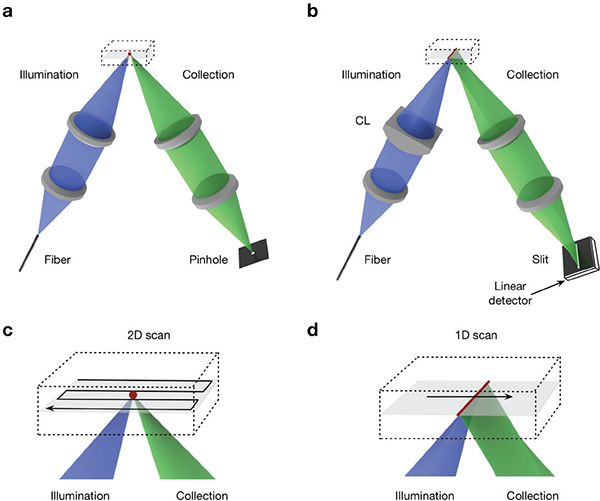
Fig. 4.

(a) In a point-scanned DAC system, light is tightly focused to a point within the sample, and a pinhole is used for confocal detection. To create an image, the point is scanned in two dimensions (e.g. following a raster- or Lissajous-scanned trajectory) and the image is generated point by point. (b) In the case of a line-scanned DAC system, the illumination objective lens is replaced with a cylindrical lens (CL) so that light is focused to a thin line within the sample, and a slit is used for confocal detection. The focal line only needs to be scanned in one dimension to create a 2D image. (c-d) Zoomed-in views of the scanning trajectories described in (a) and (b) are shown, respectively.
