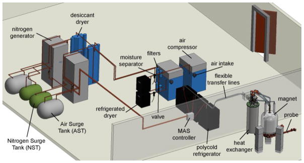
Figure 2. Physical layout of nitrogen generation system.
CAD image displays the physical layout of the entire nitrogen generation system from Fig. 1c and its coupling to the nitrogen cooling system and NMR probe. The components labeled as filters contain both the BX and DX filters.

