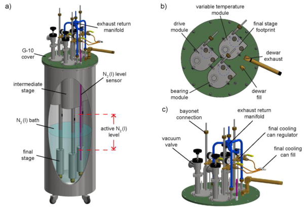
Figure 3. Heat exchanger assembly.
a) CAD image displaying the insertion of the individual modules into the liquid nitrogen dewar with the lower section submerged in liquid nitrogen bath. b) Top section view displaying the eclipse of the intermediate stage with the final stage (blue dashed circle) projected to the top surface of the intermediate stage. c) Top section of the heat exchanger assembly highlights the installment of the exhaust return manifold.

