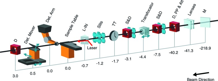
Figure 2.
Overview of the MFX instrument layout. Distances are indicated in meters from the nominal interaction region on the sample table (with the detector arm also sitting at zero, directly above the sample table); positive values indicate the direction of beam propagation. M is a mirror located in the LCLS X-ray Tunnel (XRT) with two coating stripes to provide tunable harmonic rejection and to deflect the beam to MFX. Lenses at −41.3 are pre-focusing compound refractive lenses. D, PP & Att at −40.2 is a diagnostic section which includes a Ce:YAG screen for beam viewing, a single-pulse picker and a set of ten independent silicon attenuators of various thicknesses. S&D are slits, a beam-viewing YAG screen diagnostic and a non-destructive intensity measurement diagnostic. A transfocator system is used to mount ten independent stacks of compound refractive lenses to produce a controllable spot size at the sample. TT is a timetool measuring the arrival time of the optical laser in reference to the X-rays (not yet available at MFX but expected in the future). The slits at location −1.2 are double slits to allow for blocking the harmonics of the beam. L-IN is the laser in-coupling for the optical laser. D at 3.0 is a beam-viewing Ce:YAG screen diagnostic to view the beam after it passes through the hole in the detector. The sample at the MFX instrument (0.0 on this figure) is located approximately 420 m downstream of the X-ray source which is within the undulator.

