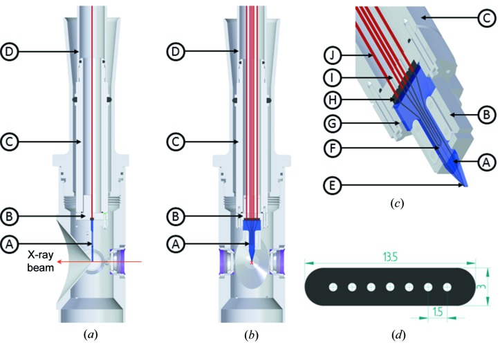
Figure 3.
(a) Sectional side and (b) along the beam views of the microfluidics integrated into the SPB/SFX instrument. The magenta arrow represents the X-ray direction. The microfluidic device (A) and inline connector (B) are attached via a connector nut (C) fitting on the 25 mm OD nozzle rod (D) through M23 external threads. (c) Detailed view of microfluidic device and inline connector. The capillaries (J) are pushed into a seven-way gasket (H) and clamped by bolting the microfluidic device holder (G) with the connector for the capillaries (I) pressed against it. The microfluidic device has a mixing module (F) and a nozzle module (E) integrated. (d) Sectional view of the gasket shows dimensions defining the constraints for design of the microfluidic device.

