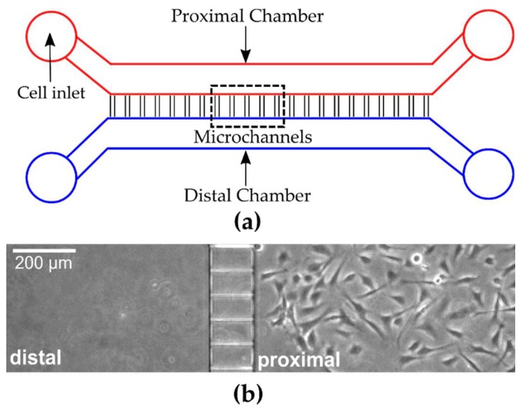
Figure 1.
Schematic illustration of microfluidic device. (a) Representative drawing of PDMS based microfluidic device with distinct proximal and distal chambers. The red region indicates the proximal chamber in which the cells are seeded and is connected to a distal chamber (blue region) by an array of microchannels. (b) Phase contrast image of a section of the proximal and distal chamber after myoblast seeding in the proximal chamber.

