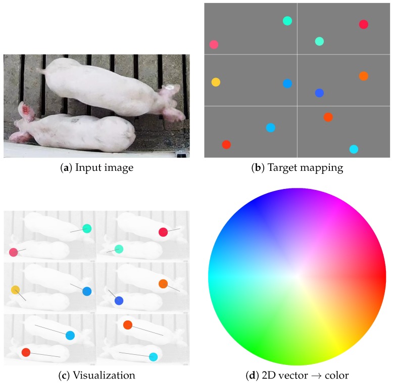
Figure 3.
The original image (a) is mapped to a 12-channel output (b), where vectors joining three pairs of body parts are encoded into circular regions in channels 5–16 of the output. Note that the four colors used in (b) are purely for visualization of the direction and magnitude of the vectors, where (d) provides a mapping between vectors and colors. The overlay in (c) is provided to illustrate the locations of the vector encodings and their magnitude and direction (illustrated by the gray line) in relation to the original image.

