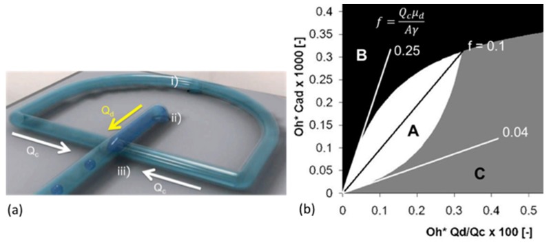
Figure 29.
The microfluidic system and flow parameters that determine effective droplet formation. (a) Schematic 3D picture of droplet formation showing the arrangement of the two inlet tubes: (i) continuous phase inlet that then splits into two tubes; (ii) dispersed phase inlet; (iii) mixing head. (bottom) High-speed microscope image of the single-channel production window. (b) Flow map, depicting all combinations of liquid properties, microchannel size and flow rates. Combinations in the white area (region A) yield the desired process, i.e., spherical particles; combinations in the black area (region B) lead to instabilities and non-uniform droplets; and, in the grey area (region C), to droplets larger than the exit channel. From Kinoshita et al. [7].

