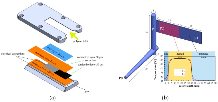
Figure 1.
(a) Schematic drawing of the mold insert adopted to layer the heater below the cavity surface; (b) Sketch of the cavity adopted for the injection molding experiments (measures are in mm), pressure transducer positions (P0–P3) are indicated. A sketch of the surface temperature profile along the flow path is also reported.

