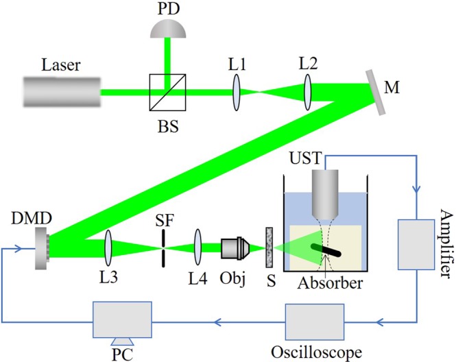
Figure 4.

Experimental setup. BS: Beam splitter; PD: Photodiode; L1, L2, L3, L4: Lens; M: Mirror; SF: Spatial filter; Obj: Objective; S: Sample; UST: Ultrasound transducer; The absorber is embedded in an agarose gel and placed in a water tank. The absorber is perpendicular to both the laser irradiation direction and the axial direction of the ultrasonic transducer. The blue line in the figure denotes the circuit part in the experiment.
